Rockwell Automation VSM500 Integrated Drive/Motor User Manual
Page 59
Step 9 - Check the Installation
9-3
9.3.1 Rotating the Cover
Before rotating the cover, take the following precautions:
Step 1. Turn off, lockout, and tag AC input power to the drive.
Step 2. Remove the cover by loosening the four cover screws. Note that the display
board ribbon cable is designed to disconnect when the cover is removed.
Step 3. Wait five minutes after disconnecting power and verify that DC bus voltage is
zero. See figure 5.1 for the location of the DC bus test points.
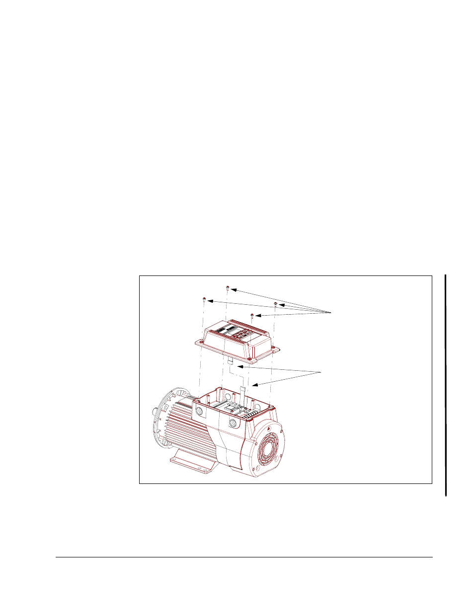
Refer to figure 9.2 and use the following procedure to rotate the cover:
Step 1. Remove the display board ribbon cable from the display board. You will need
to insert a small screwdriver into the cable latch to release it from the board.
Step 2. Insert the display board ribbon cable into the opposite side of the display
board. Push the cable in until it clicks. Verify the connection by lightly tugging
on the cable.
Step 3. Rotate the cover.
Step 4. Connect the display board ribbon cable together.
Step 5. Position the cover and tighten the four cover screws. The tightening torque
limit for the cover screws is 1.3 to 1.7 Nm (11 to 15 in-lb). Verify that all four
screws are securely tightened before applying power.
Figure 9.2 – Rotating the Cover
Cover Screws (4)
Display Board
Ribbon Cable Connector