Che c k lis t-2, Control signal terminal block connections, Ac input power connections – Rockwell Automation VSM500 Integrated Drive/Motor User Manual
Page 10
Che
c
k
lis
t-2
In
s
talling and
Operati
n
g the V
S
M
500 Int
egr
at
ed
Drive/Motor, V
e
rsion
3.
0
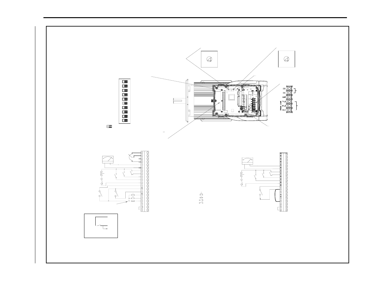
3>Important: To stop the unit using the terminal
1> The jumper between terminals 7 and 11
must be removed when wiring the
Function Loss input. See section 7.1 for
more information.
2> An external 0 to 10 volt or 4 to 20 mA
speed reference source can be connected.
See section 7.5.3 for more information.
2>
2> Parameter Settings from Setup Switches
1> Start from Operator Controls
input.
device such as PLC
Connect to external
1 10 Volt Reference
4 Common
5 0 to 10V Output
2 0 to 10V Spd Ref Input
3 4 to 20 mA Spd Ref Input
16 Start
17 Stop
7 24V DC
13 24V DC
8 Speed Preset 2
9 Speed Preset 1
10 Speed Preset 0
11 Function Loss
12 RPM / %Load Display
14 Forward/Reverse
15 Reset
18 24 DC Common
19 N.O. Relay
20 Relay Common
6 Common
6 Common
Reverse Disabled (Reverse Lockout)
Ramp-to-Rest Stop
Constant Torque Curve
Auto Restart Enabled
Relay Output Control: Faulted
Power-Up Start Enabled
1 = 1800 RPM (60 Hz) (Default)
2 = 2100 RPM (70 Hz)
3 = 2400 RPM (80 Hz)
4 = 2700 RPM (90 Hz)
5 = 3000 RPM (100 Hz)
6 = 3300 RPM (110 Hz)
7 = 3600 RPM (120 Hz)
0 = 1500 RPM (50 Hz)
input.
device such as PLC
Connect to external
2> Switch 10 is used only with the DeviceNet Communication Option board.
1> Switches 2 and 9 are used only with local operator control units.
Connector
7 = 90 sec
6 = 60 sec
5 = 30 sec
4 = 20 sec
3 = 15 sec
2 = 10 sec
1 = 5 sec (Default)
0 = 1 sec accel / 5 sec decel
(Stop to Max Spd)
Standard Unit
Local Operator Control Unit
+ -
%LOAD
RPM
1>
Parameter Settings from EEPROM Memory
Start from Terminal Block
Auto Restart Disabled
Variable Torque Curve
Power-Up Start Disabled
Relay Output Control: Running
1> Spd Ref from Operator Controls
Analog Spd Ref from Terminal Block
Coast-to-Rest Stop
Reverse Enabled
0 Hz Minimum Speed
Min Spd from Terminal Block Inputs
Start
Momentary 3-Wire
Ground
1 10 Volt Reference
+10VDC
3 4 to 20 mA Spd Ref Input
2 0 to 10V Spd Ref Input
4 Common
8 Speed Preset 2
1>
7 24V DC
5 0 to 10V Output
9 Speed Preset 1
5K
2>
FWD
+ -
REV
13
RPM
%LOAD
16
17
Start
Maintained 2-Wire
= N.C. Momentary Contact
= Maintained Contact - Closed
= Maintained Contact - Open
= N.O. Momentary Contact
Control Signal Terminal Block Connections
20 Relay Common
19 N.O. Relay
18 24 DC Common
17 Stop
16 Start
15 Reset
14 Forward/Reverse
13 24V DC
11 Function Loss
10 Speed Preset 0
12 RPM / %Load Display
AC Inputs
DC Bus (Do Not Wire)
AC Input Power
Connections
- DBR (Do Not Wire)
Display Board
With Cover Removed
Top View of Unit
Setup Slide Switch
Max Speed Switch
Accel / Decel Switch
3>
3>
6
0
7
2
1
5
4
3
7
0
1
5
4
3
2
6
10
9
O
1
N
23
5
4
7
68
= Default Setting (OFF Position)
block inputs, the jumper between terminals 13 and
17 must be removed when wiring the Stop input. See
section 7.6 for more information.