Rockwell Automation VSM500 Integrated Drive/Motor User Manual
Page 38
7-8
Installing and Operating the VSM500 Integrated Drive/Motor, Version 3.0
7.5.1 Wiring the Preset Speed Inputs
Control terminals 8, 9, and 10 select seven preset speeds as shown in table 7.1. Note
that if you select a preset speed that is greater than the maximum speed setting
(based on the rotary switch setting), the unit uses the maximum speed setting value.
Important: Slide switch position 8 defines whether terminals 8, 9, and 10 are used as
presets (default) or to define the unit’s minimum speed (user option).
Refer to section 8.3.8 for information about using terminals 8, 9, and 10 to
select minimum speed.
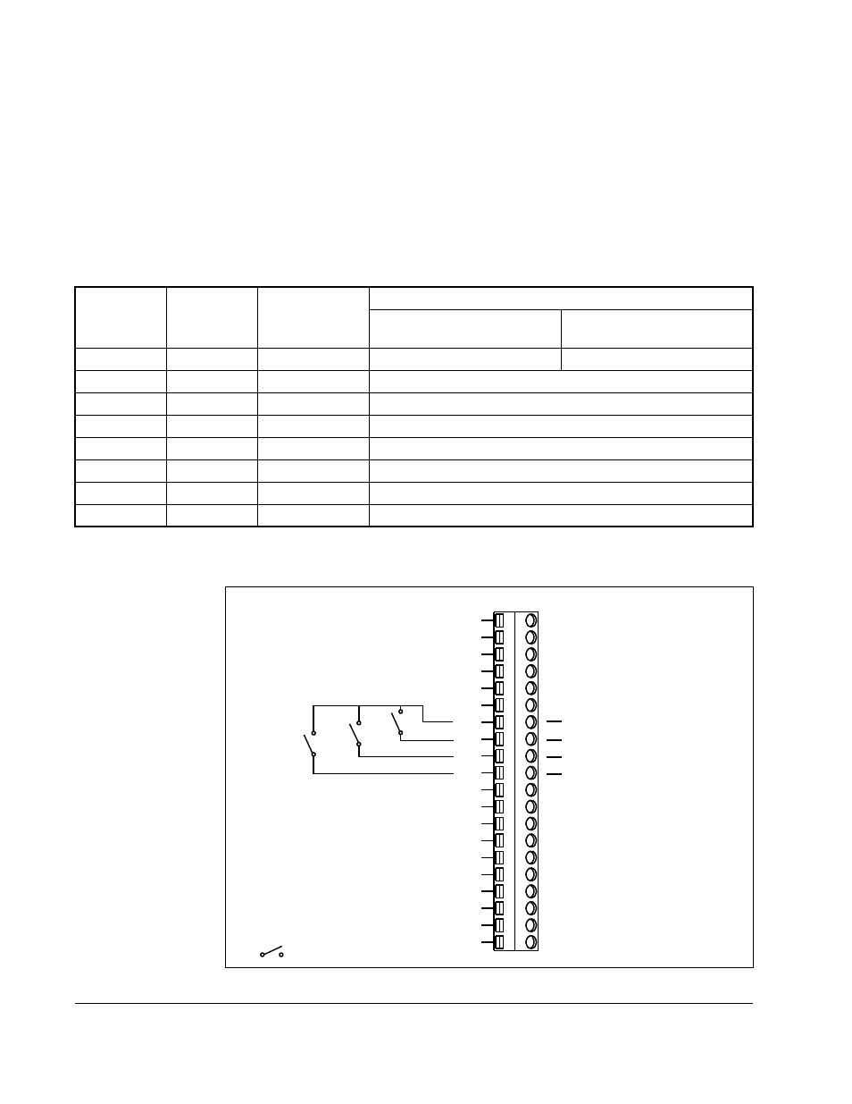
To use the preset speeds to set the speed reference, wire to terminals 8, 9, and 10 as
shown in figure 7.8.
Table 7.1 – Fixed Preset Speed Selections
Selected Speed Reference
Terminal 8
Status
Terminal 9
Status
Terminal 10
Status
Standard Unit
Local Operator
Control Unit
Open
Open
Open
Analog speed reference
Local operator control
Open
Open
Closed
Preset 1 - 300 RPM (10 Hz)
Open
Closed
Open
Preset 2 - 600 RPM (20 Hz)
Open
Closed
Closed
Preset 3 - 900 RPM (30 Hz)
Closed
Open
Open
Preset 4 - 1200 RPM (40 Hz)
Closed
Open
Closed
Preset 5 - 1500 RPM (50 Hz)
Closed
Closed
Open
Preset 6 - 1800 RPM (60 Hz)
Closed
Closed
Closed
Preset 7 - 2100 RPM (70 Hz)
Figure 7.8 – Preset Speed Input Wiring
19
18
17
16
15
14
13
12
11
10
9
8
7
6
5
4
3
2
1
Speed Preset 0
Speed Preset 1
Speed Preset 2
24V DC
= Maintained Contact - Open
20