1 local operator control unit key descriptions, 2 local operating control unit display description – Rockwell Automation VSM500 Integrated Drive/Motor User Manual
Page 14
1-4
Installing and Operating the VSM500 Integrated Drive/Motor, Version 3.0
1.2.1 Local Operator Control Unit Key Descriptions
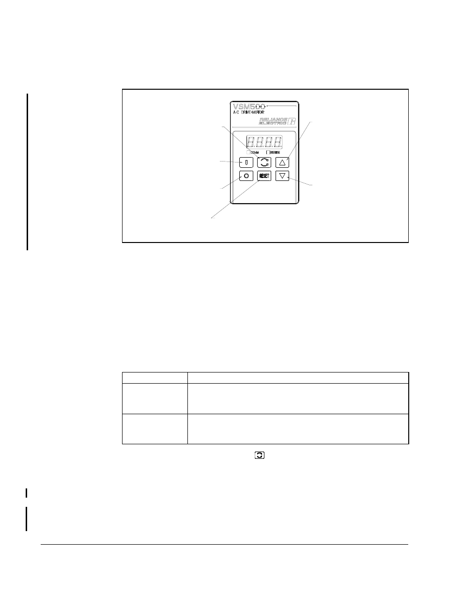
Figure 1.3 shows each key’s function.
1.2.2 Local Operating Control Unit Display Description
The four-character, seven-segment display shows output speed in RPM or %load, the
current speed reference, and active fault codes. Speed in RPM is the default display.
To display %load, see section 7.4.
If a fault occurs, the unit displays the corresponding fault code. Refer to chapter 11 for
more information about fault codes and corrective actions.
1.2.3 Local Operating Control Unit Reverse LED Description
The REVERSE LED indicates the requested direction of motor rotation:
Note that if the motor is turning and the
key is pressed, the LED turns on or off
immediately even though it may take some time for the motor to decelerate and begin
turning in the opposite direction.
1.2.4 Local Operator Control Unit Communications LED Description
The communications LED (COMM) is used only with the VSM500 DeviceNet option.
Refer to the VSM500 DeviceNet Option Board instruction manual, D2-3463, for more
information about this LED.
Figure 1.3 – Local Operator Controls Key Functions
Use the START key to apply
power to the motor section.
Use the STOP key to turn off
the drive section output to the
motor section.
Use the FORWARD/REVERSE key
to toggle the direction of motor
rotation.
Use the RESET key to reset
any active faults or cancel an
Press the UP ARROW key once to
display the current speed reference.
Hold this key down to increase
the speed reference value. The
longer this key is pressed, the
faster the reference value will
change.
faster the reference value will
longer this key is pressed, the
the speed reference value. The
Hold this key down to decrease
Press the DOWN ARROW key once to
change.
display the current speed reference.
Auto Restart sequence.
LED Status
Definition
OFF
The requested direction of motor rotation is forward.
(The VSM500 unit is shipped with the forward direction defined as
CCW shaft rotation as viewed from the motor shaft end.)
ON
The requested direction of motor rotation is reverse.
(The VSM500 unit is shipped with the reverse direction defined as
CCW shaft rotation as viewed from the motor shaft end.)