Hapter, Step 2 - plan the installation – Rockwell Automation VSM500 Integrated Drive/Motor User Manual
Page 17
Step 2 - Plan the Installation
2-1
C
HAPTER
2
Step 2 - Plan the Installation
It is the user’s responsibility to ensure that this equipment is installed properly
according to this manual and in conformance with all applicable codes. Consult your
local inspecting agency for information about any local, national, or international
codes that may apply.
Review all installation and wiring instructions thoroughly before proceeding.
Throughout the installation procedures, use figure 2.1 to locate wiring termination
points and setup switches.
If the VSM500 unit installation must be in compliance with the European Community
Electromagnetic Compatibility Standards, refer to appendix F before proceeding.
!
ATTENTION: Only qualified electrical personnel, familiar with the
construction and operation of this equipment and the hazards involved,
should install, adjust, operate, and/or service this equipment. Read and
understand this instruction manual in its entirety before proceeding.
Failure to observe this precaution could result in severe bodily injury or
loss of life.
ATTENTION: This equipment is at line voltage when AC power is
connected. Disconnect and lockout all ungrounded conductors of the
AC power line before working on the unit. Failure to observe these
precautions could result in severe bodily injury or loss of life.
ATTENTION: The user is responsible for conforming with all applicable
local, national, and international codes. Failure to observe this
precaution could result in personal injury and/or damage to, or
destruction of, the equipment.
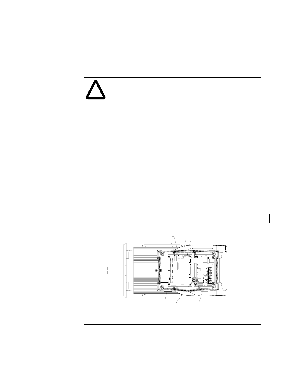
Figure 2.1 – Component Location
Accel/Decel Switch
Display Board Connector
Ground
Control Signal
Terminal Block
Max Speed Switch
Setup Slide Switch
AC Input Power
Terminal Block
Top View of Unit with
Drive Section Cover Removed