User wiring for local operator control units, Control signal terminal block connections, Local operator control unit – Rockwell Automation VSM500 Integrated Drive/Motor User Manual
Page 33
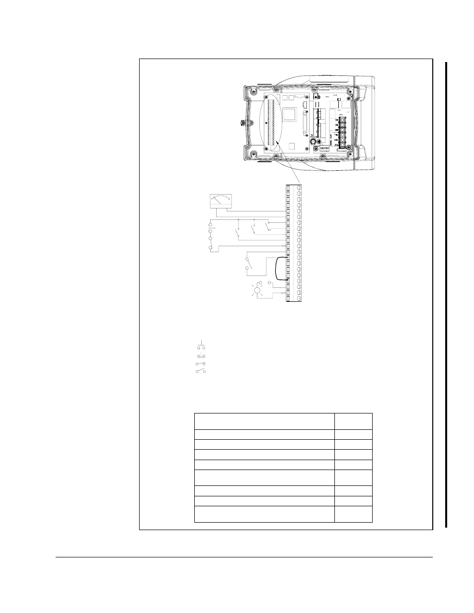
Step 7 - Wire the Control Signal Terminal Block
7-3
Figure 7.3 – Typical Control Signal Connections for Local Operator Control Units
User Wiring for Local Operator Control Units
Signal
Refer to
Section
Function Loss
7.1
Analog Output
7.2
Relay Control Output
7.3
RPM / %Load Display
7.4
Speed Reference (select one)
(default = local operator controls)
Preset Speeds
7.5.1
Speed Potentiometer
7.5.2
External Speed Reference
(0 to 10 VDC or 4 to 20 mA)
7.5.3
Drive Section with Cover Removed
Control Signal Terminal Block Connections
1>
RPM
%LOAD
+
8 Speed Preset 2
20 Relay Common
11 Function Loss
12 RPM / %Load Display
13 24V DC
14 Forward/Reverse
18 24V DC Common
19 N.O. Relay
9 Speed Preset 1
10 Speed Preset 0
15 Reset
17 Stop
16 Start
3 4 to 20 mA Speed Reference Input
2 0 to 10V Speed Reference Input
1 10 Volt Reference
4 Common
6 Common
7 24V DC
5 0 to 10V Output
Local Operator Control Unit
=
N.O. Momentary Contact
=
Maintained Contact - Open
=
Maintained Contact - Closed
=
N.C. Momentary Contact
_
1> The jumper between terminals 7 and 11
must be removed when wiring the Function
Loss input. See section 7.1 for more
information.
2> An external 0 to 10 volt or 40 to 20 mA
speed reference source can be connected.
See section 7.5.3 for more information.
3> Important: To stop the unit using the
terminal block inputs, the jumper between
terminals 13 and 17 must be removed when
wiring the Stop input. See section 7.6 for
more information.
2>
3>