1 vsm500 standard unit, 1 standard unit display description, 2 standard unit reverse led description – Rockwell Automation VSM500 Integrated Drive/Motor User Manual
Page 12
1-2
Installing and Operating the VSM500 Integrated Drive/Motor, Version 3.0
1.1
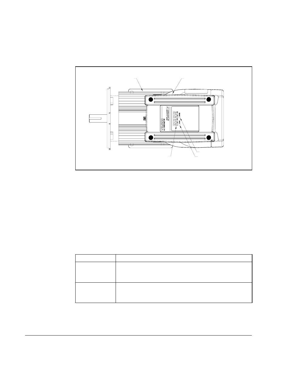
VSM500 Standard Unit
The standard unit, shown in figure 1.1, provides a local display for speed or %load,
and diagnostic information. A control signal terminal block in the drive section
connects to a user-supplied remote operator control station.
1.1.1 Standard Unit Display Description
The four-character, seven-segment display shows the drive’s output speed in RPM or
%load, and displays active fault codes. Speed in RPM is the default display. To display
%load, see section 7.4.
If a fault occurs, the unit displays the corresponding fault code. Refer to chapter 11 for
more information about fault codes and corrective actions.
1.1.2 Standard Unit Reverse LED Description
The REVERSE LED indicates the requested direction of motor rotation:
Note that if the motor is turning and you request a change to motor direction, the LED
turns on or off immediately even though it may take some time for the motor to
decelerate and begin turning in the opposite direction.
Figure 1.1 – VSM500 Standard Unit
Motor Section
Drive Section
Display
Reverse LED
Communications LED
LED Status
Definition
OFF
The requested direction of motor rotation is forward.
(The VSM500 unit is shipped with the forward direction defined
as CCW shaft rotation as viewed from the motor shaft end.)
ON
The requested direction of motor rotation is reverse.
(The VSM500 unit is shipped with the reverse direction defined
as CW shaft rotation as viewed from the motor shaft end.)