5 i/o wiring examples – Rockwell Automation SP600 User Manual Version 3.0 User Manual
Page 78
7-6
SP600 AC Drive User Manual
7.5
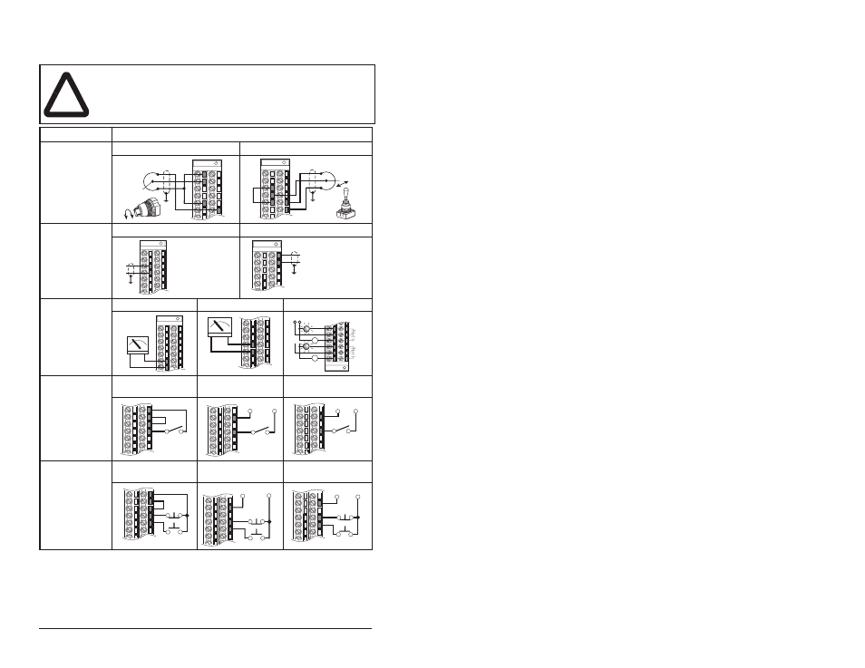
I/O Wiring Examples
!
ATTENTION: Noise and drift in sensitive bipolar input circuits
can cause unpredictable changes in motor speed and
direction. Use speed command parameters to help reduce
input source sensitivity.
Input/Output
Connection Example
Unipolar
1
10k Ohm Pot.
Recommended
(2k Ohm
Minimum)
Bipolar
1
±10V Input
1
Refer to the Attention statement at the top of this page for important bipolar wiring
information.
Potentiometer
Joystick
Analog Input
±10V Input -
100k ohm input
impedance.
4-20 mA Input -
100 ohm input
impedance
Voltage - Bipolar
1
Current - Unipolar
Analog/Digital
Output
±10V Output -
Can drive a 10k
ohm load (25 mA
short circuit
current limit).
Voltage
Current
Logic
2 Wire Control
2
- Non-Reversing
Requires 2-wire
functions only
(Digital In1 Sel).
Using 3-wire
selections will
cause a type 2
alarm.
2
Important: Programming inputs for 2-wire control deactivates all OIM Start buttons.
24VDC Internal
Supply
24VDC External
Supply
115V External
Source
3
3
Drive Model with 115V interface required. See figure 2.1.
3 Wire Control
Requires only
3-wire functions
(Digital In1 Sel).
Including 2-wire
selections will
cause a type 2
alarm.
24VDC Internal
Supply
24VDC External
Supply
115V External Source
1
2
5
22
3
5
21
22
3
4
17
18
–
+
6
7
+
–
8
9
+
–
Power Source
11
12
13
14
15
16
or
24
25
26
27
Stop-Run
25
27
Stop-Run
+24V
Common
25
27
Stop-Run
Neutral 115V
Start
24
25
26
27
28
Stop
Start
25
27
28
Stop
+24V
Common
Start
115V
Neutral
Stop
25
27
28