1 reflected wave compensation – Rockwell Automation SP600 User Manual Version 3.0 User Manual
Page 54
4-6
SP600 AC Drive User Manual
Typically, motor lead lengths less than 91 m (300 ft) are acceptable.
The primary concerns regarding cable length are cable charging
and reflected wave (see section 4.3.1).
When total lead length exceeds 300 feet, nuisance trips can occur
caused by capacitive current flow to ground. Note that these
capacitively-coupled currents should be taken into consideration
when working in areas where drives are running. If the motor lead
length must exceed these limits, the addition of output line reactors
(see section 6.3.1) or other steps must be taken to avoid problems.
Your application may be restricted to a shorter lead length due to:
•
the type of wire (shielded or unshielded)
•
the placement of wire (for example, in conduit or a cable tray)
•
the type of line reactor
•
the type of motor.
•
carrier frequency.
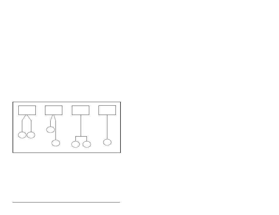
Figure 4.1 illustrates how to calculate motor lead lengths. The
examples shown assume a maximum lead length of 300 feet.
4.3.1 Reflected Wave Compensation
You must understand the effects and restrictions when applying the
drive to extended motor lead length applications. Proper cable type,
motor and drive selection is required to minimize the potential risks.
Figure 4.1 – How to Calculate Typical Motor Lead Lengths
SP600
Drive
Motor
150
′
150
′
100
′
200
′
200’
50
′
50
′
300
′
Motor
Motor
Motor
Motor
Motor
Motor
SP600
Drive
SP600
Drive
SP600
Drive