2 control and signal wire sizes, 3 recommended motor lead lengths – Rockwell Automation SP600 User Manual Version 3.0 User Manual
Page 53
Wiring Requirements for the Drive
4-5
4.2
Control and Signal Wire Sizes
The terminal block on the SP 600 I/O interface board provides
terminals for 24 V or 115 VAC power for the control inputs,
depending on the I/O card installed in the drive. Refer to 4.3 for
signal and control wiring specifications.
4.3
Recommended Motor Lead Lengths
Important:
To reduce line disturbances and noise, motor lead
length should not exceed 300 feet for any non-
Reliance Electric motor or any non-inverter duty
motor.
The length of cable between the drive and motor may be limited for
various applications reasons. The primary reasons are:
•
Reflected wave
•
Cable charging
!
ATTENTION: Verify the voltage rating of the I/O interface
board before wiring any user devices. Failure to observe this
precaution could result in damage to, or destruction of, the
equipment.
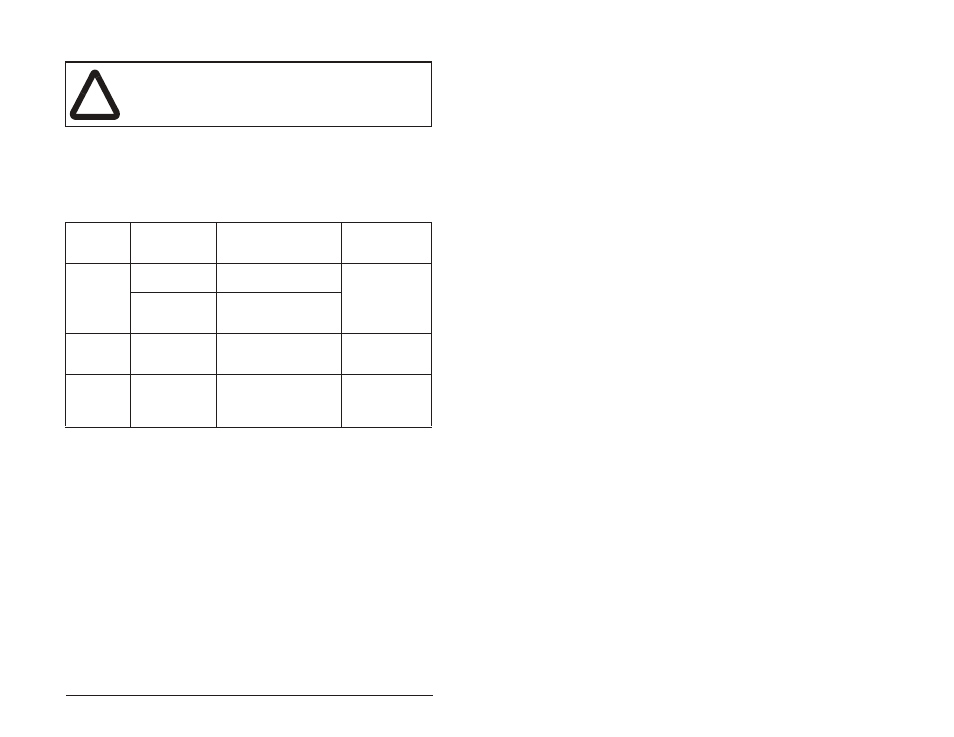
Table 4.3 – Recommended Signal and Control Wire
Signal
Type
Wire Type(s)
Description
Minimum
Insulation
Rating
Analog I/O
Belden 8760/
9460 (or equiv.)
18AWG, twisted pair,
100% shield with drain
1
.
300V, 60
°
C
(140
°
F)
Belden 8770
(or equiv.)
18AWG,
3-conductor, shielded for
remote pot only.
Unshielded
Control
Per US NEC or
applicable local
code
300V, 60
°
C
(140
°
F)
Shielded
Control
Multi-conductor
cable such as
Belden 8770
(or equiv.)
18 AWG, 3-conductor
shielded.
300V, 60
°
C
(140
°
F)
1
If the wires are short and contained within a cabinet which has no sensitive circuits,
the use of shielded wire may not be necessary, but is always recommended.