Rockwell Automation 1794-APBDPV1 FLEX I/O PROFIBUS Adapter User Manual User Manual
Page 99
Publication 1794-UM064B-EN-P - May 2014
Configure the Adapter for Master/Slave Communication 87
The format of the adapter status word is defined in the following table:
The adapter expects the identifier area for each of the eight FLEX I/O slots to be
2 bytes. The DP input/output identifier and all specific DP identifiers (except
the empty module) are not supported.
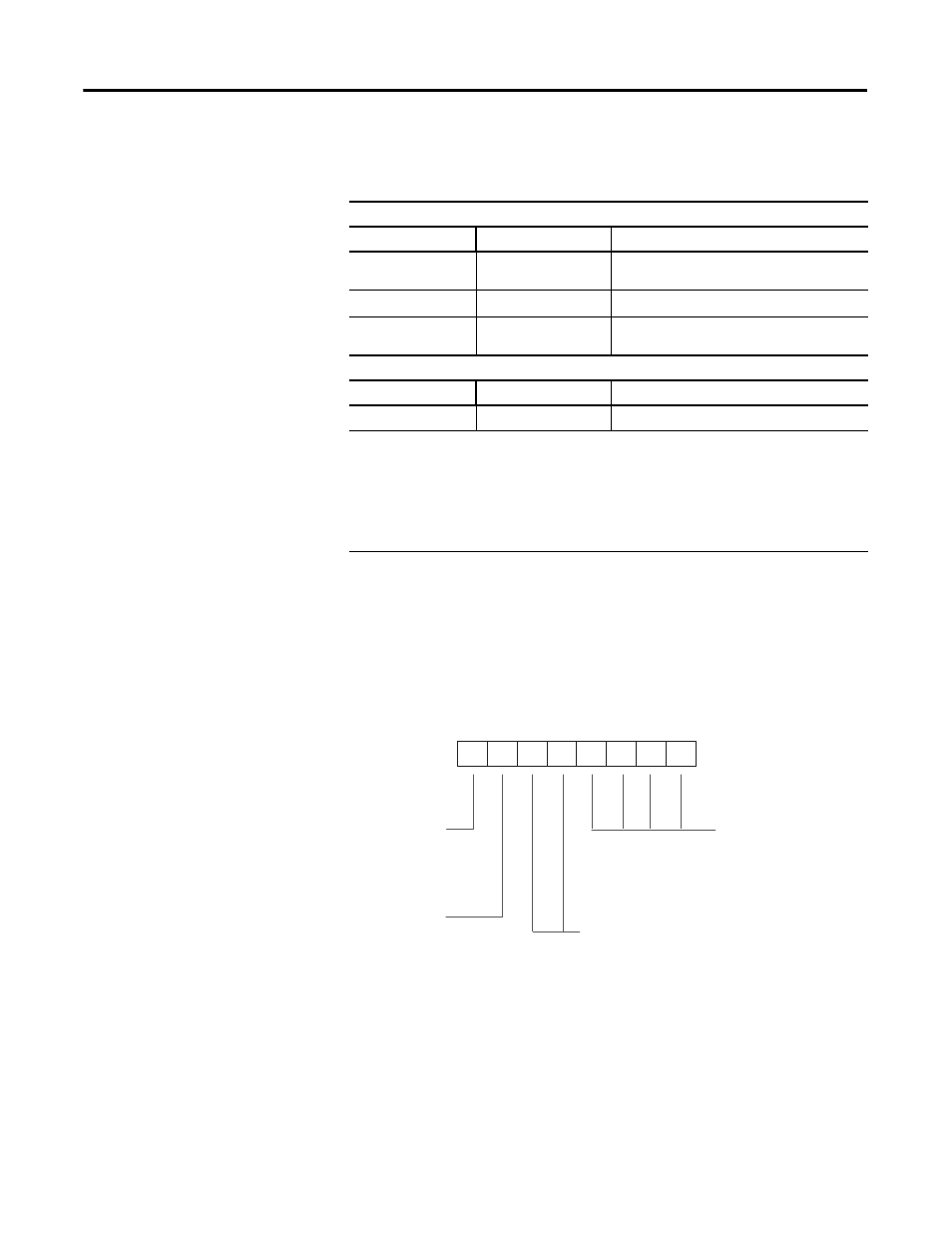
The identifier byte and its format are described in the following illustration. This
byte is defined in Part 3 of the PROFIBUS Standard.
Adapter Status Word
Input Status Word
Bit Position
Name
Description
0
Address Change
This bit is set when the Node Address switch is
changed since power up.
1…7
Reserved
Sent as zeroes.
8…15
I/O Module Fault
This bit is set when an error is detected in a slot
position (bits 0…7 refer to slots 1…8).
Output Status Word
Bit Position
Name
Description
0…15
Reserved
sent as zeroes.
I/O Module Faults are caused by:
• transmission errors on the FLEX I/O backplane
• bad module
• removed module
• incorrect module inserted
Most Significant Bit
Bit Number
Consistency over
0 byte
or
word
1 whole
length
length format
0 byte
byte structure
1 word word structure
input/output
00 specific identifier formats
01 input
10 output
11 input-output
Length of data
00 1 byte resp. 1 word
15 16 byte resp. 16 words
7
6
5
4
3
2
1
0
Least Significant Bit
•
•
•
1160