Rockwell Automation 1794-APBDPV1 FLEX I/O PROFIBUS Adapter User Manual User Manual
Page 72
Publication 1794-UM064B-EN-P - May 2014
60 Communicate With Your Module
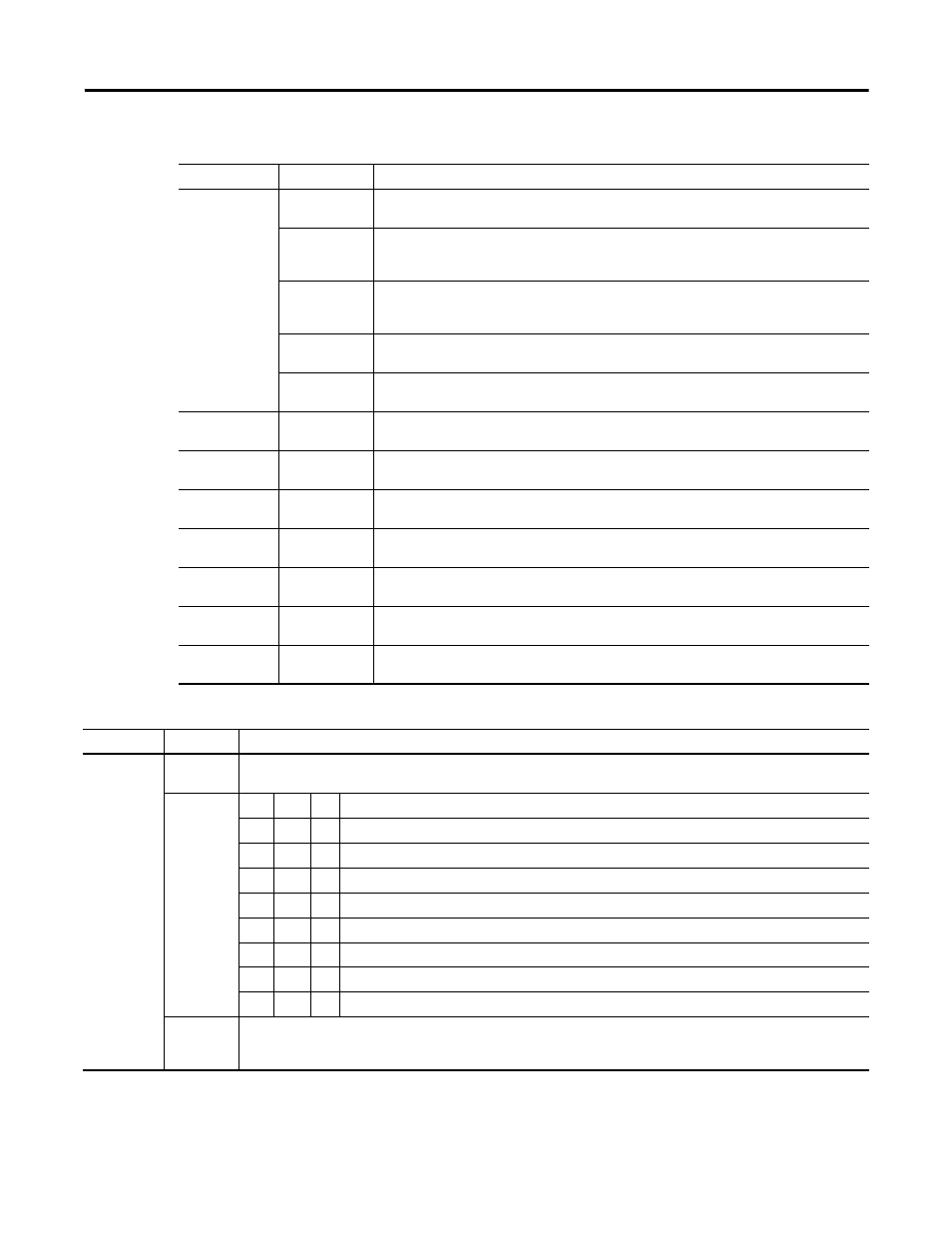
Read Word 0
Bit 11 (13)
Ch 1 Counter Stored – This bit, when set (1), indicates a counter value is saved in store 1. This
bit is reset by StoreReset.
Bit 12 (14)
Ch 0 Preset Reached (PR0) – When this bit is set (1), in all configuration modes, the counter 0
value equals the preset 0 value, either in a positive or negative direction. This bit is reset by
PresetReset0 and can only be set again after at least 1 more pulse.
Bit 13 (15)
Ch 1 Preset Reached (PR1) – When this bit is set (1), in all configuration modes, the counter 1
value equals the preset 0 value, either in a positive or negative direction. This bit is reset by
PresetReset1 and can only be set again after at least 1 more pulse.
Bit 14 (16)
Ch 0 Counter Inc/Dec – 0 = last pulse decreased counter value, 1 = last pulse increased
counter value
Bit 15 (17)
Ch 1 Counter In/Dec – 0 = last pulse decreased counter value, 1 = last pulse increased counter
value
Read Word 1
Bits 00…15
(00…17)
Ch 0 Stored Counter – Saved counter value on channel 0.
Read Word 2
Bits 00…15
(00…17)
Ch 1 Stored Counter – Saved counter value on channel 1.
Read Word 3
Bits 00…15
(00…17)
Ch 0 Counter – Current value in counter 0.
Read Word 4
Bits 00…15
(00…17)
Ch 1 Counter – Current value in counter 1.
Read Word 5
Bits 00…15
(00…17)
Ch 0 Counter Readback – Counter word readback – last value written to write word 1.
Read Word 7
Bits 00…15
(00…17)
Ch 1 Counter Readback – Counter word readback – last value written to write word 2.
Read Word 8
Bits 00…15
(00…17)
Firmware Revision – identification of latest software version code.
1794-ID2 Pulse Counter Module Word/Bit Definitions for Block Transfer Read Words
Word
Bit
Definition
Write Word 0 0…15
(0…17)
Ch 0 Control – Control word for setting the function of Ch 0 Counter.
Bits 00…02
02
01
00
Ch 0 Mode Selection bits
0
0
0
Counting on positive (rising) edge of input signal A (Up/dwn counting determined by B).
0
0
1
Quadrature encoder X1.
0
1
0
Quadrature encoder X2.
0
1
1
Quadrature encoder X4.
1
0
0
Counting up on positive edge of input signal A, and down on positive edge of input signal B.
1
0
1
No count function.
1
1
0
No count function.
1
1
1
No count function.
Bit 03
Ch 0 Counter Preset bit – A positive edge on this bit moves the value in Preset X to Counter X, independent of
Preset Enable.
NOTE: To use Preset as Reset, use a count value of 0000 in the Preset value word.
1794-ID2 Pulse Counter Module Word/Bit Definitions for Block Transfer Read Words
Word
Bit
Definition