Rockwell Automation 1794-APBDPV1 FLEX I/O PROFIBUS Adapter User Manual User Manual
Page 50
Publication 1794-UM064B-EN-P - May 2014
38 Communicate With Your Module
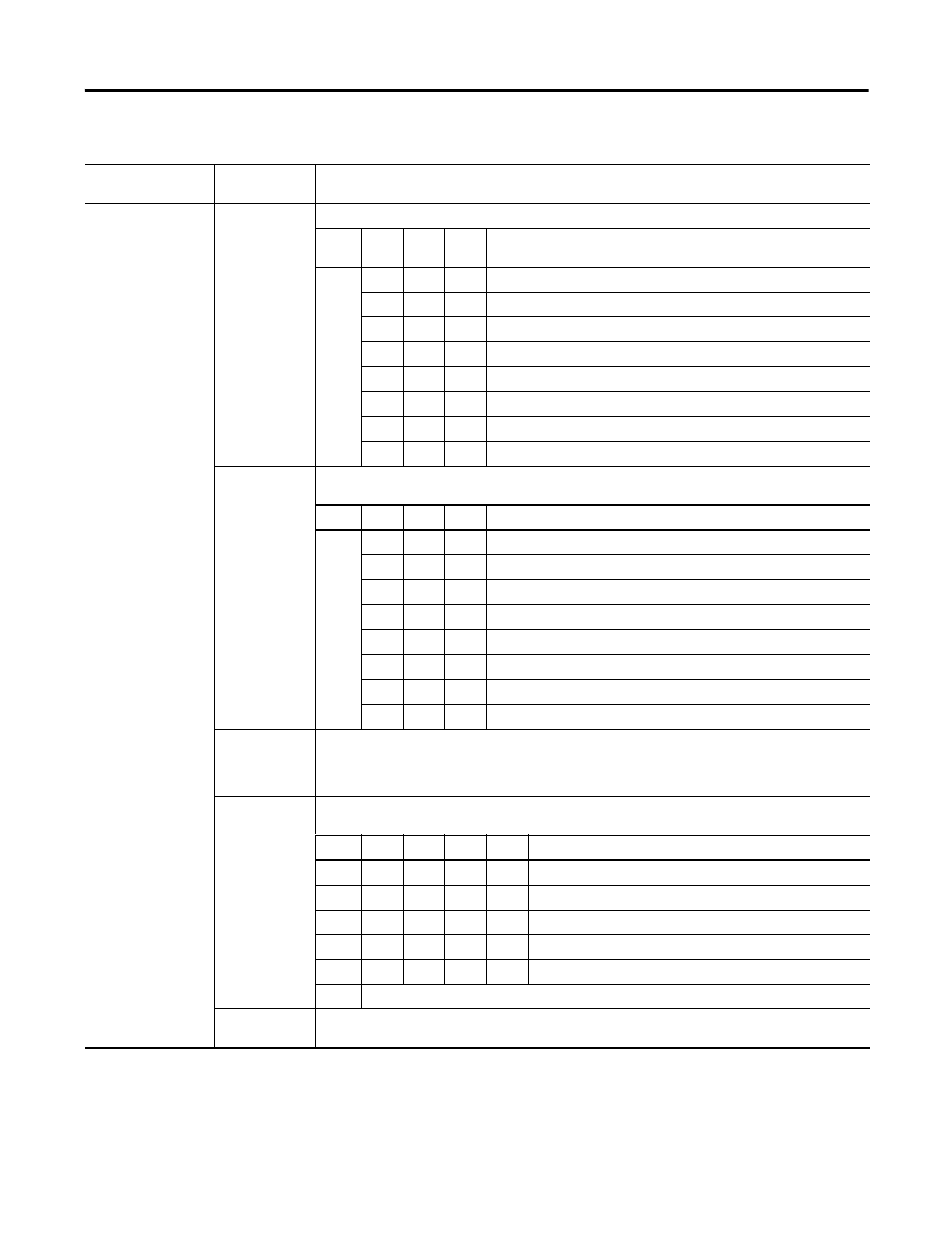
1794-IRT8 Word/Bit Descriptions for Block Transfer Words
Word
Dec. Bits
(Octal Bits)
Description
Write Word 0
00…02
Inpt Filter Cutoff Bits
Bit
02
01
00
Filter Time Constants – Actual filtering depends on the module’s mode
of operation.
0
0
0
Hardware filtering only (default filtering).
0
0
1
25 ms
0
1
0
100 ms
0
1
1
250 ms
1
0
0
500 ms
1
0
1
1 s
1
1
0
2 s
1
1
1
5 s
03…05
Reference Junction – Used when input type is set to thermocouple and sensor mode is set to internal
compensation. Sets a fixed reference junction to compensate all thermocouple channels.
Bit
05
04
03
Reference Junction
0
0
0
0 °C
0
0
1
20 °C
0
1
0
25 °C
0
1
1
30 °C
1
0
0
40 °C
1
0
1
50 °C
1
1
0
60 °C
1
1
1
70 °C
06…07
Fault Mode Bits – When a bit is set (1), fault mode is enabled for that channel. Bit 06 corresponds to
channels 0…3; bit 07 corresponds to channels 4…7.
0 = disabled
1 = enable wire-off detection
08…11
(10…13)
Data Format – Module defaults to -4000...10000 in millivolt mode, and 0...5000 in ohms mode with implied
decimal points (for example -40.00, 0.0
Ω ).
Bit
11
10
09
08
Data type for channels 0-7
0
0
0
0
°C (implies decimal point XXXX.X)
0
0
0
1
°F (implies decimal point XXXX.X)
0
0
1
0
°K (implies decimal point XXXX.X)
0
0
1
1
-32767...3267
0
1
0
0
0...65535
0101...1111 not used
12…15
(14…17)
Not used