Bandwidth and range, Profibus apbdpv1 adapter components, Diagnostic indicators – Rockwell Automation 1794-APBDPV1 FLEX I/O PROFIBUS Adapter User Manual User Manual
Page 15: Network connector, Diagnostic indicators network connector
Publication 1794-UM064B-EN-P - May 2014
Overview of the FLEX I/O PROFIBUS APBDPV1 Module 3
Bandwidth and Range
The FLEX I/O PROFIBUS APB adapter baud-rate is now 12 MBd and,
although the physically PROFIBUS address range is still limited to 1..99, the
logical address range is 1..126.
PROFIBUS APBDPV1
Adapter Components
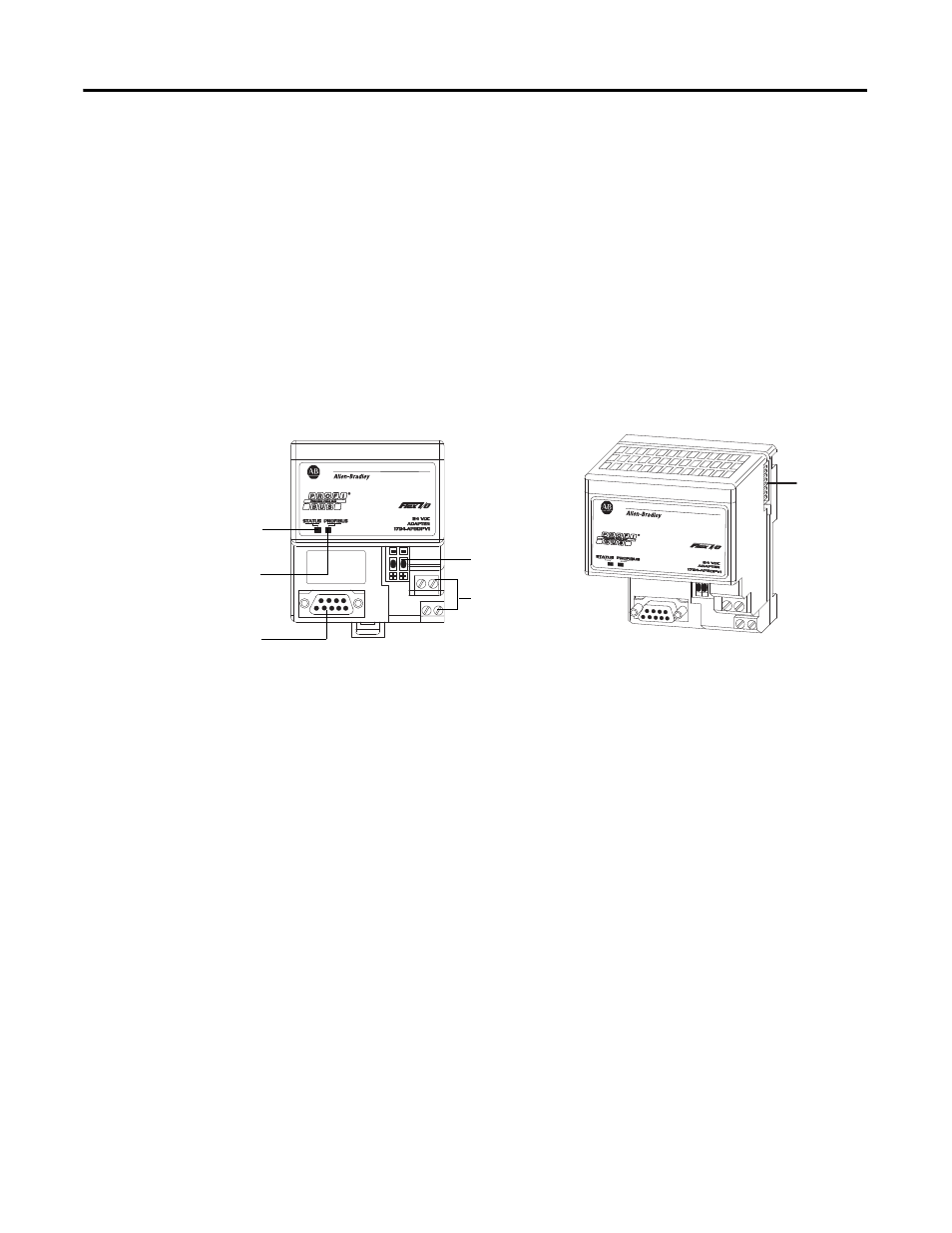
The adapter module consists of the following components:
• two diagnostic indicators
• PROFIBUS DP network connector
• 24V DC power wiring connection terminals
• two node address switches
Diagnostic Indicators
Diagnostic indicators are located on the front panel of the adapter module. They
show both normal operation and error conditions in your FLEX I/O system. The
indicators are:
• Device status (STATUS)
• Communication link status (PROFIBUS)
Upon power-up, the adapter goes to an initialization state and performs a self-test
(memory check, data memory clear, CRC on code). The indicators also go
through a self-test sequence. If a failure occurs, the adapter transitions to a faulted
state and waits for reset (cycle power). Otherwise, the adapter begins monitoring
the network (run state) for messages.
Network Connector
Use the 9-pin SUB-D connector to connect your adapter to the PROFIBUS
network.
1119
1120
Status indicator
(green/red)
PROFIBUS indicator
(green/red)
PROFIBUS DP
network
connector
FlexBus
connector
24V DC wiring
connection
terminals
Node address
switches