Rockwell Automation 1794-APBDPV1 FLEX I/O PROFIBUS Adapter User Manual User Manual
Page 73
Publication 1794-UM064B-EN-P - May 2014
Communicate With Your Module 61
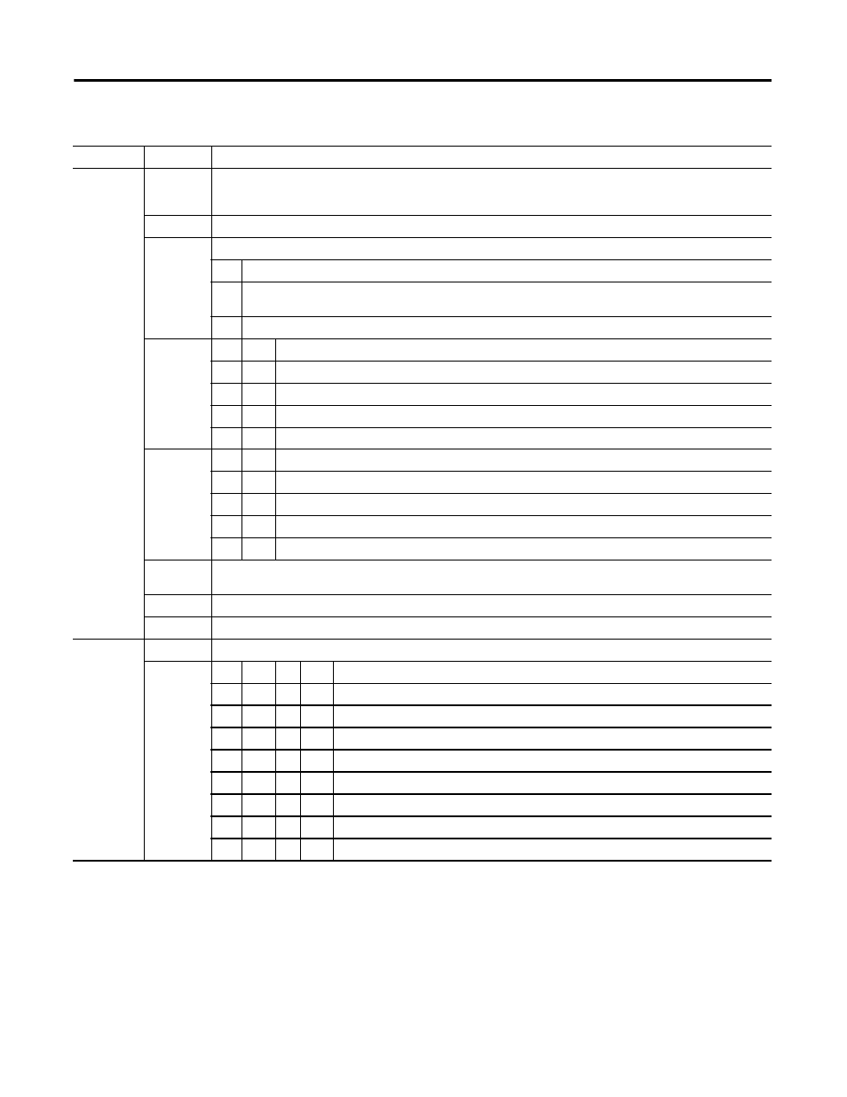
Write Word 1 Bit 04
Ch 0 Z Preset Enable bit – When this bit is set (1), a positive edge on Z preloads Counter X = Preset X, independent of
Cal Enable.
NOTE: If Z is configured to do Store and Preset (Reset), the Store will occur first.
Bit 05
Ch 0 Count Enable bit – When this is set (1), the incremental encoder is enabled.
Bits 06…08
(06…10)
Ch 0 Calibration Control bits – bits 06, 07 and 08.
06
Cal Enable bit – When set (1), the counter can be calibrated.
07
Cal Direction bit – When set (1), calibration is performed in a negative direction; when reset (0), calibration is
performed in a positive direction.
08
Ch 0 Cal Reset bit – Calibration is acknowledged and a new calibration is enabled on a positive edge on this bit.
Bits 09…10
(11…12)
10
09
Gate Control bits
0
0
No gate function on input G.
0
1
Counting only if G is high (active).
1
0
Counting only if G is low (inactive).
1
1
The counter can be calibrated when G is high (active).
Bits 11…12
(13…14)
12
11
Store Control bits
Save the counter value on positive edge of Z (if Stored X = 0).
Save the counter value on positive edge of G (if Stored X = 0).
Save the counter value on negative edge of G (if Stored X = 0).
Save the counter value on positive and negative edges of G (if Stored X = 0).
Bit 13 (15)
Ch 0 Rollover bit – When set (1), the counter counts up to the prset and then restarts at 0. If this bit is reset (0) (not
rollover), the rollover preset value = FFFF (hex = 65536 (decimal).
Bit 14 (16)
Ch 0 Store Reset bit – A positive edge on this bit resets Stored X in Signals.
Bit 15 (17)
Ch 0 Preset Reset bit – A positive edge on this bit resets Preset Detected in Signals.
Write Word 2
Ch 1 Control – Control word for setting the fuction of Ch 1 Counter.
Bits 00…02
Bit
02
01
00
Ch 1 Mode Selection bits
0
0
0
Counting on positive (rising) edge of input signal A (up/dwn counting determined by B).
0
0
1
Quadrature encoder X1.
0
1
0
Quadrature encoder X2.
0
1
1
Quadrature encoder X4.
1
0
0
Counting up on the positive edge of input signal A, and down on positive edge of input signal B.
1
0
1
No count function.
1
1
0
No count function.
1
1
1
No count function.
1794-ID2 Pulse Counter Module Word/Bit Definitions for Block Transfer Read Words
Word
Bit
Definition