Tachometer feedback board, Encoder options – Rockwell Automation 7000A PowerFlex Medium Voltage AC Drive - Air-Cooled (A Frame) User Manual
Page 330
5-88
Component Definition and Maintenance
7000A-RM001A-EN-P – January 2011
7000 “A” Frame
Tachometer Feedback Board
Encoder
Options
There are two positional encoder interface boards that may be used with the
PowerFlex 7000 Forge Control. The encoder interface boards do not have
any user accessible test points; however, buffered and isolated versions of
each of the signals A+, A-, B+, B-, Z+ and Z- are available on the ACB at
test points TP45-TP50.
Regardless of which type of encoder board, the following conditions
should be adhered to:
1.
Do not attach encoders with open collector outputs to the drive.
Acceptable outputs are Analog Line Driver or Push Pull.
2.
The drive will not operate properly if using single ended Quadrature
encoders. Rockwell Automation recommends using differential inputs
only for these types of encoders. Single ended outputs are only
acceptable for Positional Encoders.
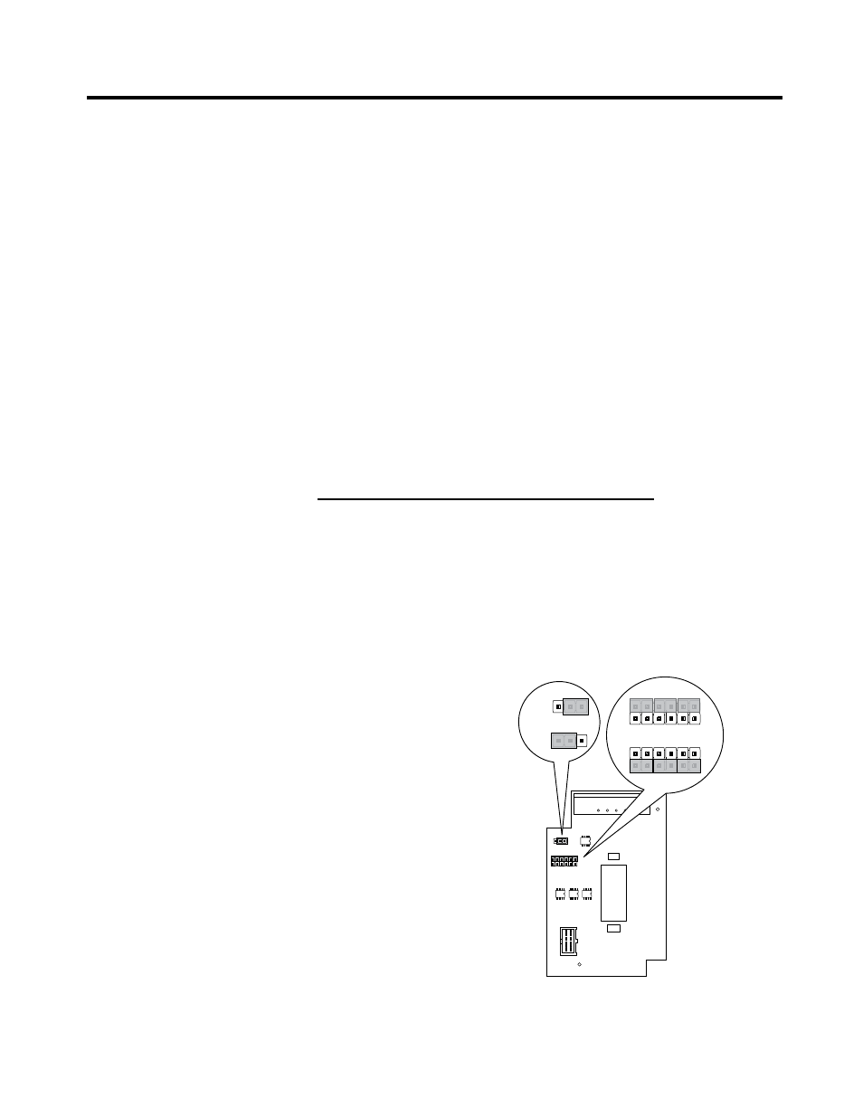
20B-ENC-1 & 20B-ENC-1-MX3 Encoder Interface
This encoder interface allows the drive to be connected to a standard
Quadrature Encoder. The 20B-ENC encoder interface provides 3 optically
isolated differential encoder inputs for A and B phases as well as a Z
track. These inputs cannot be configured for use with a single ended
Encoder. Differential encoders only are supported. The board also
provides a galvanically isolated 12V/3Watt supply to power the attached
encoder. The 20B-ENC-1 Encoder interface may be configured for +5V
operation, however Rockwell recommends operation at 12V.
J3
J3
J2
+1
2V
1
2
3
12
11
21
+5VR
EF
1
2
3
+5V
+12V
1
2
3
+12V
+5V
12
11
21
12
11
21
Output
Config.
J2
Intput
Config.
Note: Must be configured
for 12V operation.
Figure 5.67 – Encoder Interface (20B-ENC-1 and 20B-ENC-1-MX3)