Three-phase input/single phase input, Power supply tests, Circuit board healthy lights – Rockwell Automation 7000A PowerFlex Medium Voltage AC Drive - Air-Cooled (A Frame) User Manual
Page 190
4-36 Commissioning
7000A-RM001A-EN-P – January 2011
7000 “A” Frame
Three-Phase Input / Single Phase Input
This configuration has one source of control power:
•
Three-phase control power for fan operation which is also
converted to single-phase control power to operate the Interface,
power supplies, I/O and additional auxiliaries.
Similar to the three-phase configuration, the input power for the fan
and control must be verified at the primary of DS1.
If the ratings match the designation on the electrical schematic, it is
acceptable to apply control power to the drive by closing CB1 and
DS1. Take necessary measures to rectify the control power levels in
the event that they do not meet the design specifications.
Power Supply Tests
The variety of components installed within the PowerFlex 7000 “B”
Frame requires a versatile control distribution design. As a result
there are many power supplies incorporated within the drive design.
The following section describes how to verify that all power supplies
installed within the drive are functioning as designed.
Circuit Board Healthy Lights
Once all sources of control power have been verified and proven to be
within specified levels, close the low voltage input breaker (CB1) and
Disconnect Switch (DIS); doing so will apply control power to the drive.
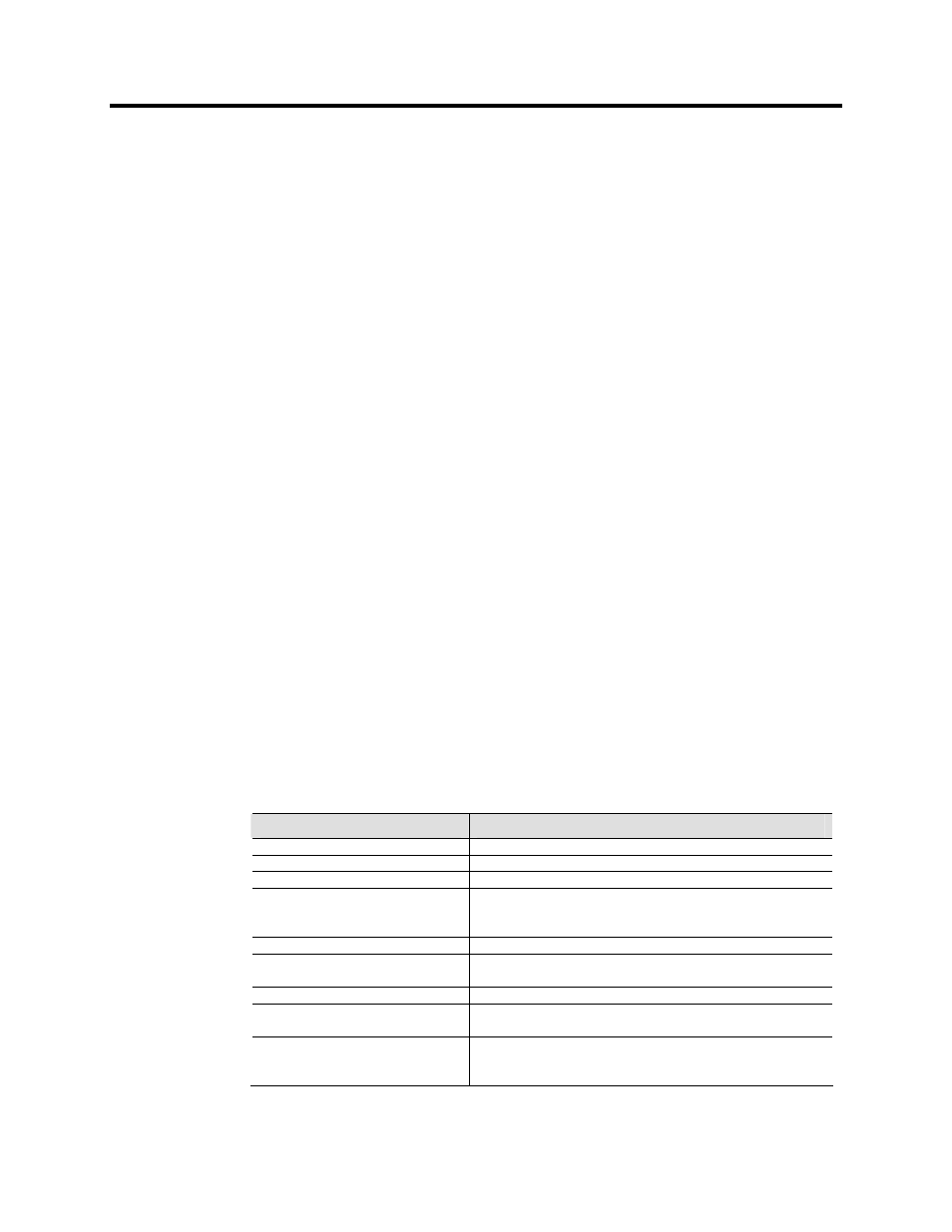
Observe the healthy lights on all drive control boards to ensure that
the unit has passed all power-up self-tests. The following table
identifies the LEDs that should be illuminated, assuming the drive
passes all self-tests and is in a ready state:
Component
LED Activated
AC/DC Converter Power Supply
No Healthy LEDs Provided
DC/DC Converter Power Supply
No Healthy LEDs provided
SGCT Power Supplies
1 Green LED per section of Power Supply (No Label)
SGCT Integrated Firing Card
LED 4 (Green)
LED 3 (Green)
LED 1 (Red)
Analog Control Board (ACB)
2 Green LEDs – Healthy
DPM
LED 6 (Green)
LED 9 (Green)
LED 7 (Green)
LED 11 (Green)
External I/O
Various YELLOW Surface Mounted LEDs based on I/O status
Remote I/O Adapter
LED configuration will change based on adapter. Refer to the
adapter user's manual to identify the state the adapter is in.
Operator Interface Terminal
Displays Boot Sequence. Communications Error will occur in a fault
situation. A small flashing indicator in bottom right corner indicates
good communication.
Number of supplies varies based on drive configuration.