Sgct and snubber circuit – Rockwell Automation 7000A PowerFlex Medium Voltage AC Drive - Air-Cooled (A Frame) User Manual
Page 258
5-16
Component Definition and Maintenance
7000A-RM001A-EN-P – January 2011
7000 “A” Frame
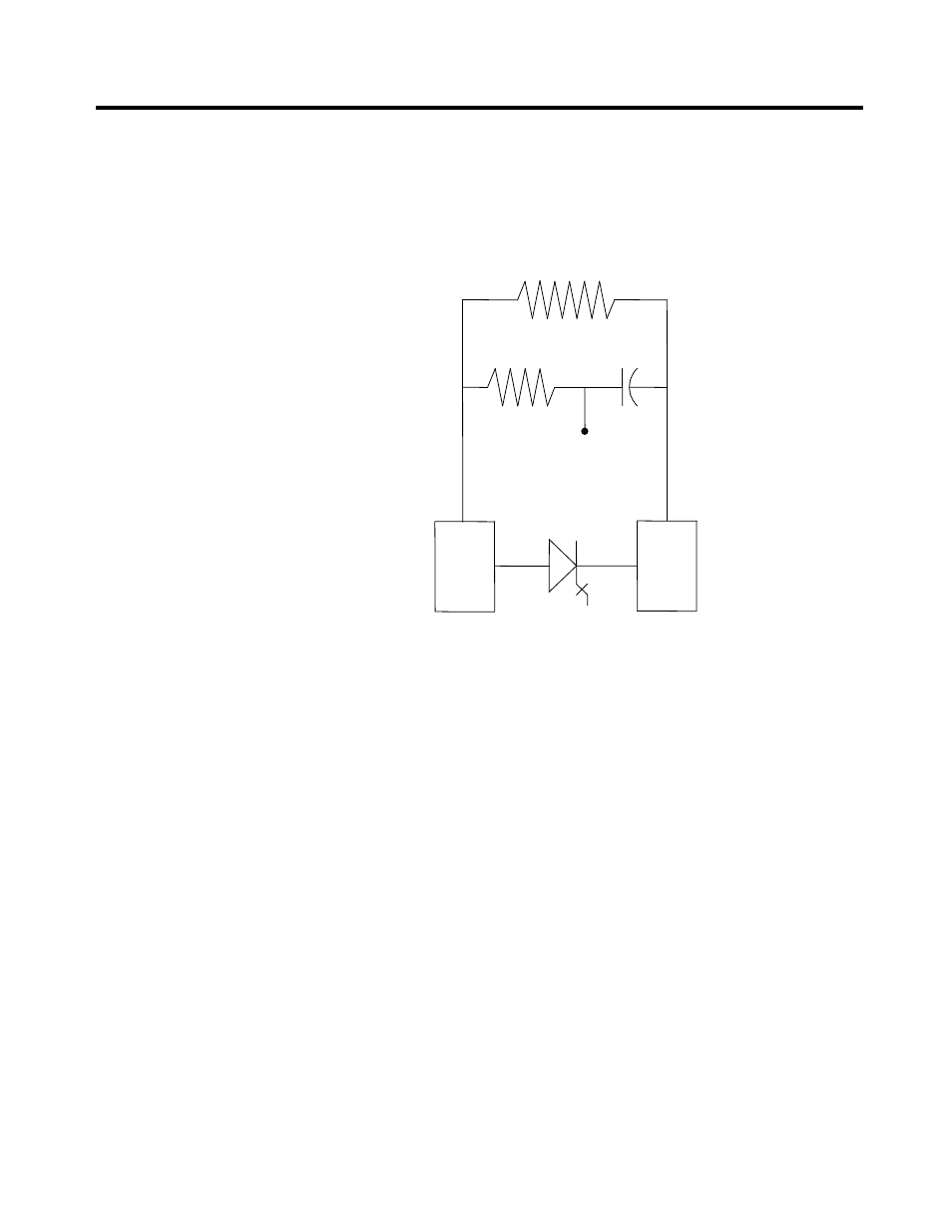
SGCT and Snubber Circuit
As with all power semi-conductor or thyristors, the SGCT must have a
snubber circuit. The snubber circuit for the SGCT is comprised of a
snubber resistor in series with a snubber capacitor.
SHARING
RESISTOR
SNUBBER
RESISTOR
SNUBBER
CAPACITOR
TEST
POINT
HEAT
SINK
HEAT
SINK
SGCT
Figure 5.14 – SGCT and snubber circuit
In addition to the snubber circuit, a sharing resistor is connected in
parallel with the SGCT. The function of the sharing resistor is to ensure
the voltage is shared equally among the SGCTs when connected in series.
SGCTs are connected in series to increase the total reverse voltage
blocking (PIV) capacity as seen by the electrical circuit. A single SGCT
has a PIV rating of 6500 V. This single device will provide sufficient
design margin for electrical systems with 2400 V medium voltage supply.
At 4160 V, 2 SGCTs must be connected in series to provide a net PIV of
13000 V to achieve the necessary design margin. Similarly, three SGCTs
must be connected in series at 6600 V, providing a net PIV of 19500 V to
achieve the necessary design margin.
The cooling requirements of the SGCT are achieved by placing the SGCT
between two forced air-cooled heatsinks, one heatsink on the anode and
the other heatsink on the cathode. The clamp assembly on the right hand
side of the inverter module generates these forces.