Rockwell Automation 7000A PowerFlex Medium Voltage AC Drive - Air-Cooled (A Frame) User Manual
Page 217
Commissioning 4-63
7000 “A” Frame
7000A-RM001A-EN-P – January 2011
3.
Set
parameter
Idc Test Command in Current Control to 0.225 pu
for AFE rectifier drives and 0.400pu for SCR drives.
4.
Set
parameter
CurReg Bandwidth in Current Control to 100
rad/sec. A lower than the normal bandwidth makes the step
response easier to measure.
5.
Set
parameter
T DC Link in Current Control to 0.020 sec, which
is at the low end of the normal range of values and should
produce an under-damped response.
6.
Assign
parameters
Idc Reference and Idc Feedback in the
Current Control group to 2 DPM test points e.g. RTP1 and
RTP2. This can be done similarly to the way that the meter
assignments were described earlier in the chapter. Then they can
be displayed on the oscilloscope.
7. Start the drive. Set parameter Idc Ref Step in Current Control to
0.075pu for AFE rectifier drive and 0.200 pu for SCR drives.
The dc link current will step up and down by this amount at
regular intervals.
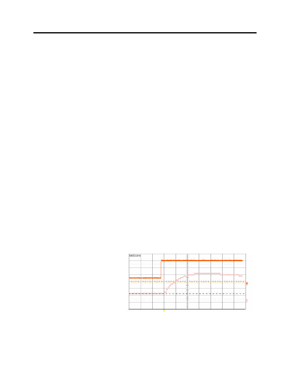
9. Adjust the scope to trigger on the rising edge of the dc current
reference and observe the dc current feedback on the other
channel. The step response will probably have noticeable
overshoot, indicating that the dc link time constant is set too low.
10.
Adjust
parameter
T DC Link until the current feedback rises to
about 63% of its final value in 10 ms as shown in the figure. The
overshoot should now be quite small. Increasing T DC Link
causes the rise time to increase. Since the desired step response
is slightly under-damped, T DC Link should not be increased
beyond the value at which the overshoot disappears.
Idc Reference
Idc Feedback
63%
0%
Figure 4.17 – Current Regulator Tuned Incorrectly