Temperature sensing (cont.) – Rockwell Automation 7000A PowerFlex Medium Voltage AC Drive - Air-Cooled (A Frame) User Manual
Page 262
5-20
Component Definition and Maintenance
7000A-RM001A-EN-P – January 2011
7000 “A” Frame
4. Remove the device (SGCT) that is secured to the heatsink with the
thermal sensor. (Refer to Figure 5.11, 5.12, 5.13, 5.16 or 5.17).
5. Disconnect the fiber optic cable to the temperature feedback board.
6. Remove two M8 screws holding the heatsink in place.
7. Remove the heatsink with the temperature feedback board from the
PowerCage.
8. Disconnect the plug that connects the thermal sensor to the circuit
board.
9. Remove the screw that attaches the thermal sensor to the heatsink.
10. Replace with the new thermal sensor and cable assembly.
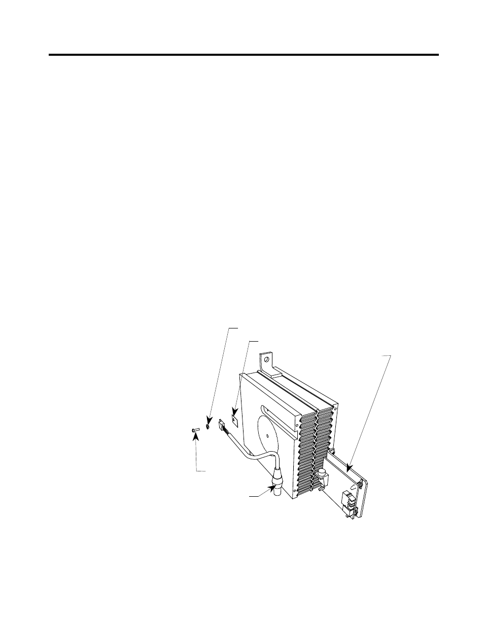
11. Note there is a small voltage difference between the thermal sensor
and its heatsink. For proper function, it is essential to mount the small
insulating pad between the thermal sensor and the heatsink and the
insulating bushing between the thermal sensor mounting screw and
the thermal sensor (see Figure 5.17).
12.
Replacement of the heatsink with the new thermal sensor is in the
reverse order of removal.
13.
Follow procedure “Uniform Clamping Pressure” to ensure the
heatsinks are clamped to a uniform pressure.
Insulating bushing
Mounting pad
Temperature feedback
circuit board
Mounting screw
Thermal sensor and
cable assembly
Figure 5.17 – Replacing the Thermal Sensor
Temperature Sensing
(cont.)