Temperature sensing – Rockwell Automation 7000A PowerFlex Medium Voltage AC Drive - Air-Cooled (A Frame) User Manual
Page 261
Component Definition and Maintenance 5-19
7000 “A” Frame
7000A-RM001A-EN-P – January 2011
I M P O R T A N T
I M P O R T A N T
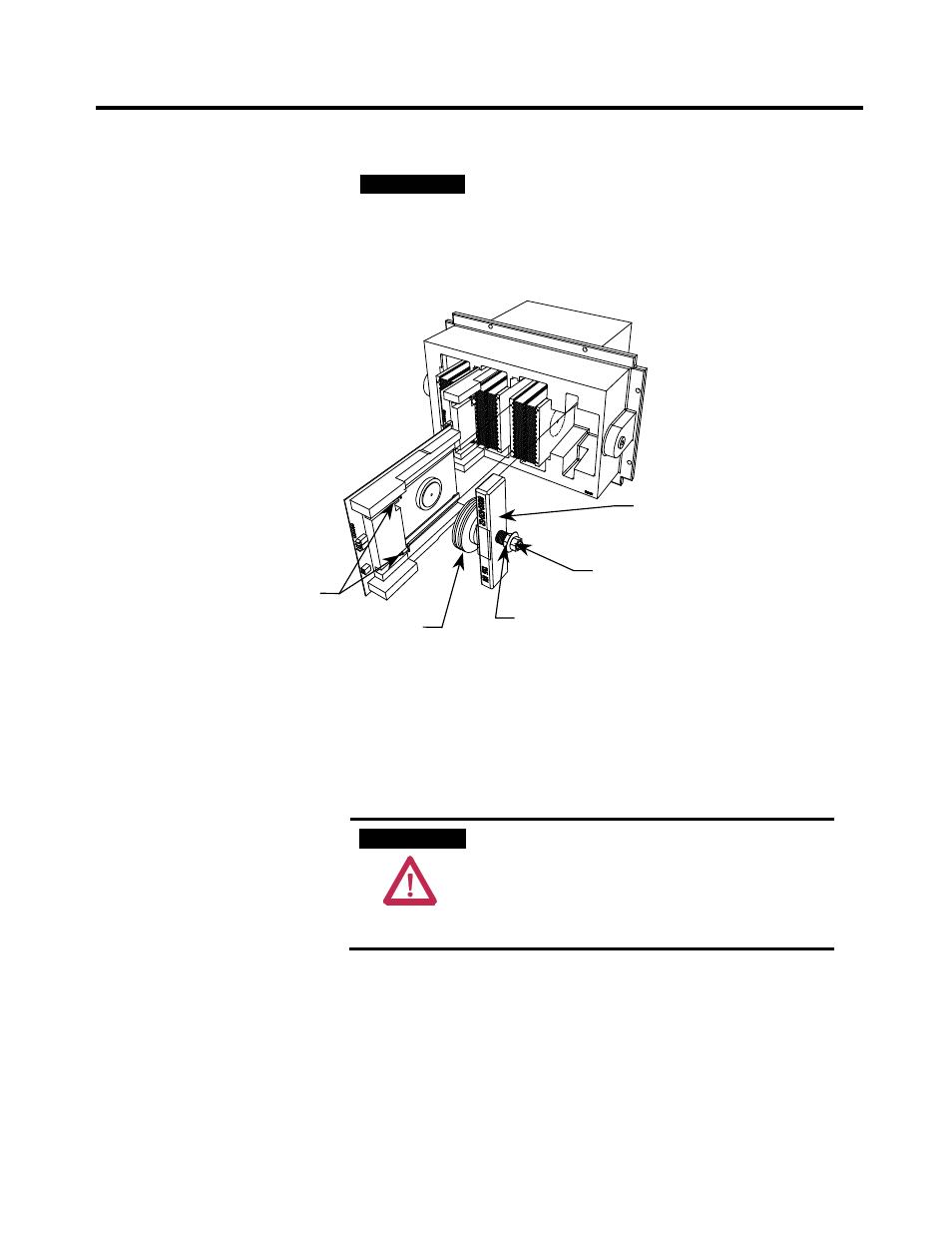
Never rotate the calibration nut located outside
the indicating washer at the end of the threaded
rod. The rotation of the outer nut will affect the
torque calibration, which is factory set. Only
adjust the inside nut. (See Figures 5.15 and 5.16.)
SGCT captive screws
Clamp head block
Disc springs
Inside nut used for loosening
and applying load to assembly
DO NOT ADJUST outside nut.
Figure 5.16 – Detail of the clamping assembly
Temperature Sensing
Thermal sensors are located on heatsink(s) in the converter. The thermal
sensor is mounted on the heatsink with the temperature feedback board.
1. Ensure there is no power to the equipment.
A T T E N T I O N
A T T E N T I O N
To prevent electrical shock, ensure the main
power has been disconnected before working on
the drive. Verify that all circuits are voltage free
using a hot stick or appropriate voltage-
measuring device. Failure to do so may result in
injury or death.
2. To replace a thermal sensor, refer to Preface page P-2, regarding
electrostatic discharge.
3. The heatsink with the thermal sensor must be removed from the
PowerCage. Remove clamp load (refer to Figure 5.15).