Dc link/fan/control components, D.c. link / fan / control components – Rockwell Automation 7000A PowerFlex Medium Voltage AC Drive - Air-Cooled (A Frame) User Manual
Page 279
Component Definition and Maintenance 5-37
7000 “A” Frame
7000A-RM001A-EN-P – January 2011
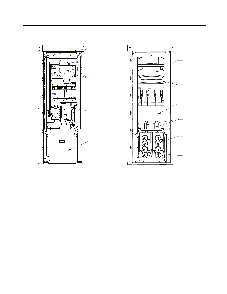
D.C. Link / Fan / Control Components
Analog
Control
Board
Medium Voltage
Barrier (for
access to
Line/Motor
Capacitors)
Low voltage
Control Tub
Retaining
Hardware
AC/DC
Power
Supply
ANALOG
CONTROL
BOARD
Fan
Inlet Ring
DC Link
Inductor
Grounding
Network/
Filter
Motor Filter
Capacitor
Line Filter
Capacitor
M+ L+ L- M-
Figure 5.30 – DC Link and Fan cabinet
with low voltage control tub shown
Figure 5.31 – DC Link and Fan Cabinet
with low voltage control tub removed
When the door is opened, control components are accessible. Behind the
low voltage swing-out panel is the medium voltage compartment where
the DC link and fan are located.
The D.C. link is mounted on the floor plate of the cabinet above the
capacitors.
Power connections are made to the inductor via its flexible leads. There
are four power connection points labeled L+, L-, M+, and M-.
The D.C. link is equipped with thermal protection for the windings.
There is a current sensor on the M+ conductor.
Above the D.C. link is the fan.
The primary elements of the fan are the inlet ring, impeller and motor.
The inlet ring is stationary and must not contact the rotating impeller.