Rockwell Automation 2098-DSD-xxx Ultra3000 Digital Servo Drives with DeviceNet User Manual
Page 81
Publication 2098-RM001C-EN-P – August 2002
Programming Reference
2-65
90
Set
Digital Output 1
Configuration
DWORD
4
Each digital output configuration parameter assigns
one or more functions to the corresponding Digital
Output (or Relay Output). Selecting a function will
cause the Digital Output to become active when the
associated function becomes active. If no functions
are selected by a digital output configuration
parameter, then the corresponding Digital Output (or
Relay Output) is unassigned.
Bit 0 = At Home
Bit 1 = End of Sequence
Bit 2 = In Motion
Bit 3 = In Dwell
Bit 4 = Registered
Bit 5 = Axis Homed
Bit 6 = Tracking
Bit 7 = Startup Commutation Done
Bit 8 = Positive Hardware Overtravel
(Motor Integral Limit)
Bit 9 = Negative Hardware Overtravel
(Motor Integral Limit)
Bit 10 = Positive Overtravel
Bit 11 = Negative Overtravel
Bit 12 = At Index 0 Position
Bit 13 = At Index 1 Position
Bit 14 = Position Compare 1
Bit 15 = Position Compare 2
Bit 16 = In Position
Bit 17 = Within Position Window
Bit 18 = Zero Speed
Bit 19 = Within Speed Window
Bit 20 = Positive Current Limit
Bit 21 = Negative Current Limit
Bit 22 = Up to Speed
Bit 23 = Drive Enabled
Bit 24 = DC Bus Charged
Bit 25 = Fault Disable
Bit 26 = Reserved
Bit 27 = Reserved
Bit 28 = Reserved
Bit 29 = Reserved
Bit 30 = Brake
Bit 31 = Ready
Default = 0x00000000
Note: Set is not allowed if the drive is enabled.
91
Set
Digital Output 2
Configuration
DWORD
4
92
Set
Digital Output 3
Configuration
DWORD
4
93
Set
Digital Output 4
Configuration
DWORD
4
94
Set
Relay Output
Configuration
DWORD
4
Parameter Object,
Instances ID = 1- 996
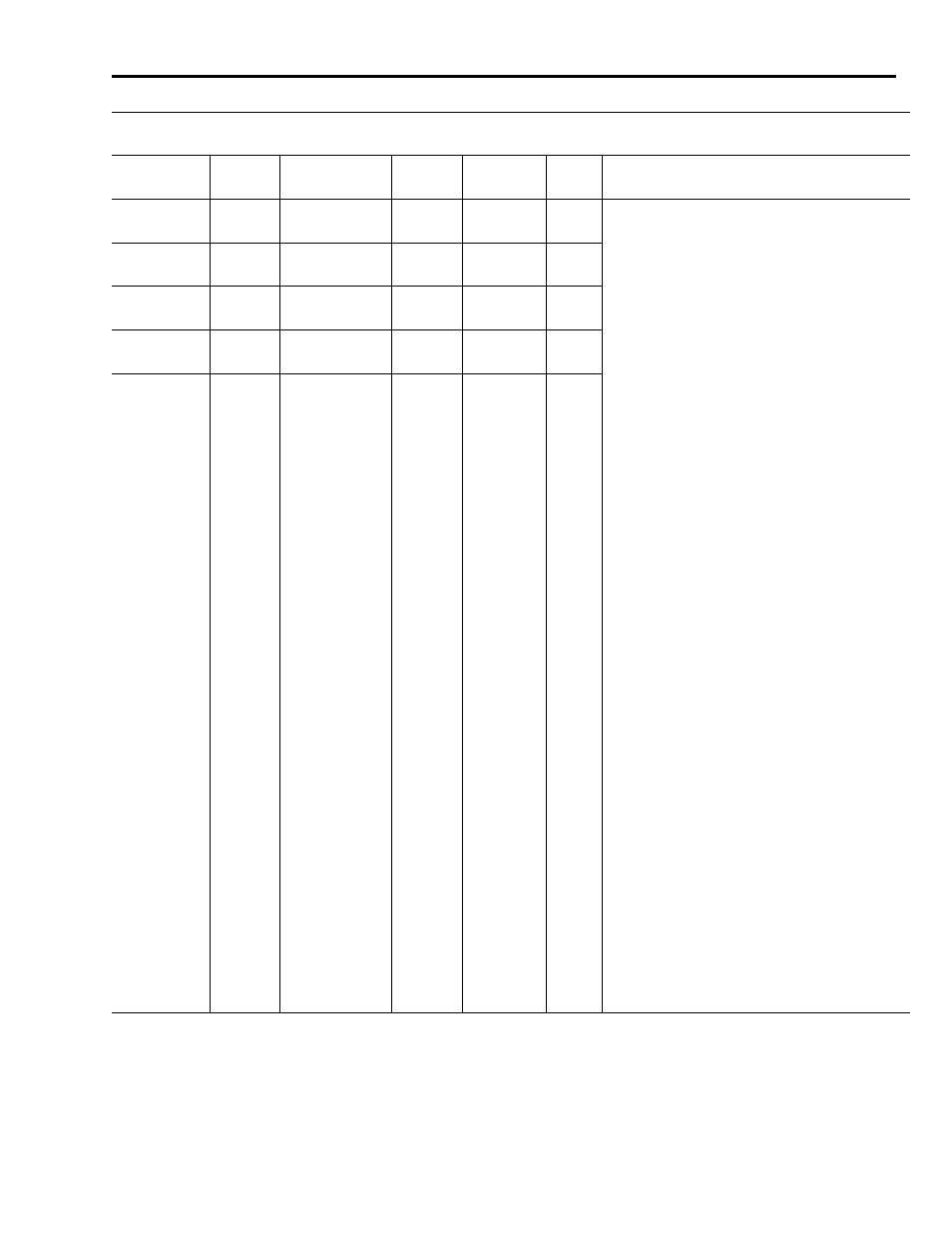
Parameter
Instance
Access
Rule
Parameter
Name
Data
Type
Data Size
(Bytes)
Units /
Scale
Description