Programming chapter 3 – Rockwell Automation 1771-PD PID MODULE (+DU) User Manual
Page 50
Programming
Chapter 3
3Ć7
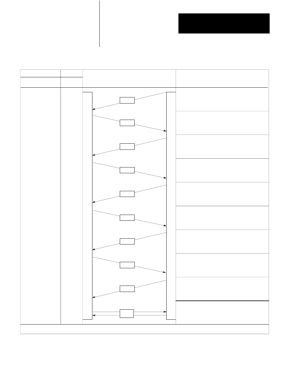
Figure 3.4
Load/Enter Sequence
Command
Load
Bit
Enter
Bit
Status
Ready
Bit
Block Transfers
read
write
Description
SB
DB
1st
SB
2nd
4th
6th
8th
9th
DB
LP1
LP2
DB
SB
3rd
5th
7th
SB
SB
SB
P
I
D
M
O
D
U
L
E
P
R
O
C
E
S
S
O
R
0
0
0
1
0
1
1
1
0
0
0
0
0
1
0
SB = Status Block, DB = Dynamic Block, LP1 and LP2 = Loop 1 and Loop 2 Parameter Blocks
11107
1st The processor reads the status block to start
the sequence.
2nd
PID module (load bit set) to transfer dynamic
The processor writes the dynamic block to the
block data.
3rd The processor reads the status block to confirm
4th The processor writes loop constants to the module
5th The processor reads the status block to confirm
6th
7th The processor reads the status block to confirm the
8th The processor writes the dynamic block to the
9th
dynamic block data and to address the next
block transfer.
to set the features for loop 1.
loop 1 constants andd to address the next
block transfer.
The processor writes loop constants to the module
to set the features for loop 2.
data for the entire sequence (readdy bit set) and to
address the next block transfer.
module to start PID control (enter bit set).
The processor reads the status block to confirm
that the module has been programmed and no
errors were detected.
Toggle sequence or periodic block transfers.