Rockwell Automation 1771-PD PID MODULE (+DU) User Manual
Page 15
Assembly and Installation
Chapter 2
2Ć2
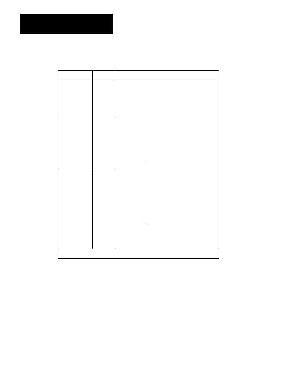
Table 2.A
Indicator Diagnostics
Indicator
State
Condition
FAULT
(red)
OFF
ON
Normal operation.
Hardware fault. Analog outputs are held at either last
state, minimum or maximum value as determined by the
userĆselected programming plugs. If this indicator is on,
the other indicators are not valid
RUN
(green)
ON
Flashing
OFF
Toggle
Normal operation
PID module is initially powered (unprogrammed and is
waiting for data from the PC processor.
PID module is not in the normal run mode.
Analog power (+15V dc) is lost when STAND ALONE
and RUN indicators are alternately toggling on and off.
STAND
ALONE
(yellow)
OFF
Flashing
Toggle
ON
Normal operation
The module is in soft mode and is controlling PID loops
independently. It is not communicating with an active PC
Processor.
NOTE: Disconnecting the field wiring arm will interrupt
PID control.
Analog power (+15V dc) is lost when STAND ALONE
and RUN indicators are alternately toggling on and off.
A programming error is causing a block transfer
communication error.
NOTE: All indicators are off when in calibration mode.
In order to accommodate a wide variety of applications, a number of
programming (jumper) plugs must be correctly positioned inside the PID
module. The following functions are user-selectable using the
programming plugs:
output range: +4 to +20mA or +1 to +5V dc
input range: +4 to +20mA or +1 to +5V dc
tieback input range: +4 to +20mA or +1 to +5V dc, if used current
output compliance: standard or additional hard fault output: hold last
value or max/min value output for loss of +5V dc: max or min value
+5V dc source: backplane or external
Internal Selections