Aseembly and installation chapter 2 – Rockwell Automation 1771-PD PID MODULE (+DU) User Manual
Page 26
Aseembly and Installation
Chapter 2
2Ć13
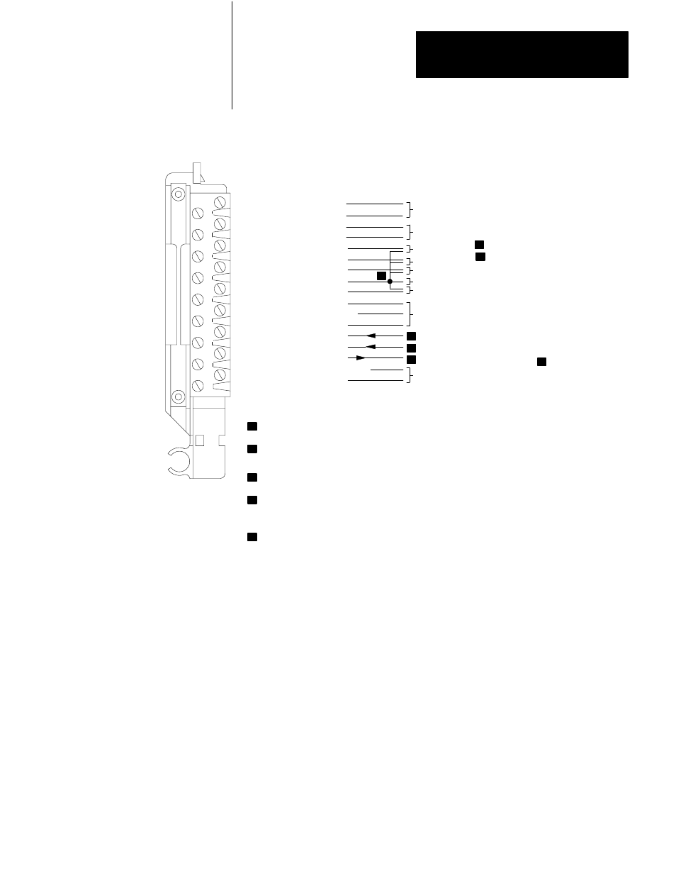
Figure 2.4
Terminal Identification and Connections
Terminal Identification
Cat. No. 1771-PDC
Terminal
Function
18
Input 1 (+ Lead)
17
Input 1 (- Lead)
16
Input 2 (+ Lead)
15
Input 2 (- Lead)
14
Tieback Input 1
13
Tieback Input 2
12
Analog Output 1
11
Module Common
10
Analog Output 2
9
+15V DC
8
15V DC Common
7
-15V DC
6
Manual Mode 1
5
Manual Mode 2
4
Manual Request
3
OPT. +5V DC Common
2
Optional +5V DC
1
Not Used
+-
Process Variable 1
Process Variable 2
Tieback Input 1
Process Variable 2
Process Variable 2
Tieback Input 2
Control Element 1
Module Common
Control Element 2
Required +15V DC Power Supply
(cat. no. 1770-P1, 1778-P2, or equivalent)
Optional +5V DC Power Supply
(cat. no. 1771-P2 or equivalent)
The tieback inputs can be used to track manual control station output to provide bumpless
transfer, or can be used as feedforward inputs.
Module common signal level can be selected to either
15V DC COMMON (system
common) for standard compliance, or -15V DC for additional compliance depending
on the application.
When the manual control station is in manual, the station switches these line to the
MODULE COMMON terminal.
When a request for manual is made from the PID module or when this relay contact output
is used for alarm annunciation, the line is switched to the module common signal level for
50 msec. For hardware failure or loss of analog power ( 15V DC), this relay output is held
at module common until the fault is corrected.
Programming plugs must be positioned for optional +5V DC supply.
+-
+-
1 1 0 9 7
3
1
1
2
3
4
5
1
2
3
4
5
1
2
3
4
5
6
7
8
9
10
11
12
13
14
15
16
17
18