Programming chapter 3 – Rockwell Automation 1771-PD PID MODULE (+DU) User Manual
Page 101
Programming
Chapter 3
3Ć58
Block transfer sequencing must be programmed for each of the following:
dynamic/status toggle sequence
power-up load/enter sequence
load/enter sequence
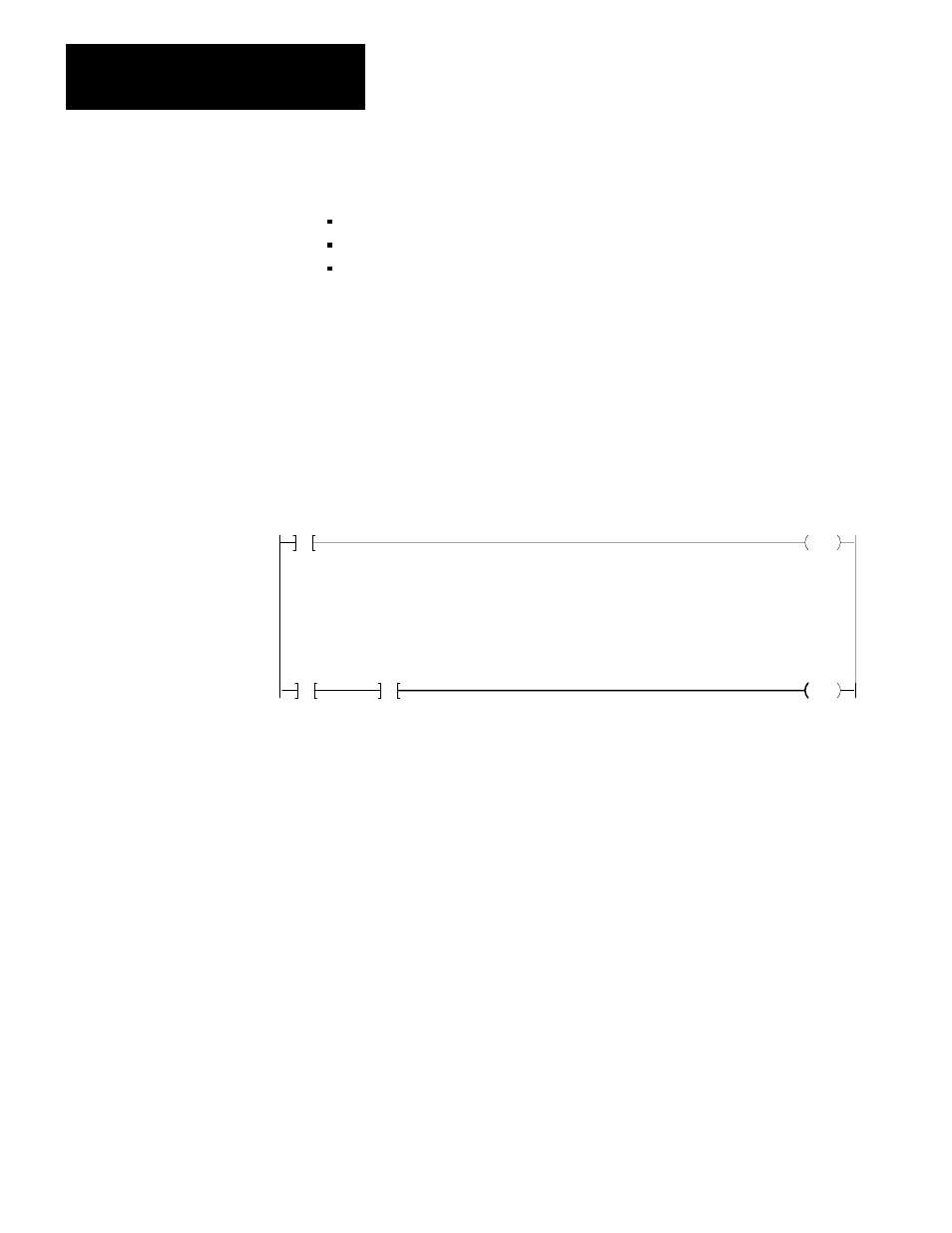
Figure 3.18
Programming the Load/Enter Sequence
351
YYY
PUT
131
YYY
The next block start address YYY in word W59 is read into data table word 351
8
when
the status block is transferred to the PC processor.
Get the file address of the next block to be transferred YYY, and put it into the file
storage location of the block transfer write instruction.
G
037
XXX
PUT
131
XXX
G
Prompt the next block transfer
Get the file address of the dynamic block XXX and put it into the file storage location of
the block transfer write instruction when the status of the powerĆup bit, W58 B13 = 1, is
read into 350/13.
350
13
11123
NOTE: Words 037, 350 and 351 can be any data table storage words
Prompt the Load Enter sequence
RUNG A
RUNG B
The term dynamic/status toggle sequence describes the operating mode of
alternating read and write block transfers. The sequence allows dynamic
block data to be changed without changing the loop constants. The status
block is read to prompt the next write block transfer and to report status,
alarm and diagnostic information. The dynamic block is transferred to
change any of the dynamic block values such as the set analog output
value, set point, proportional gain, and bias. Block transfers can occur in
only one direction at a time. Toggling implies that a read block transfer
must be completed before a write block transfer is requested.
There are a few bits which establish the module configuration which also
cannot be changed in this sequence. There are denoted by the symbol
(LE). If changes to these bits are transferred to the module, they will be
ignored until a load/enter sequence is complete. These bits are W01 B15,