Manual control station interface, 2ć17 – Rockwell Automation 1771-PD PID MODULE (+DU) User Manual
Page 30
Aseembly and Installation
Chapter 2
2Ć17
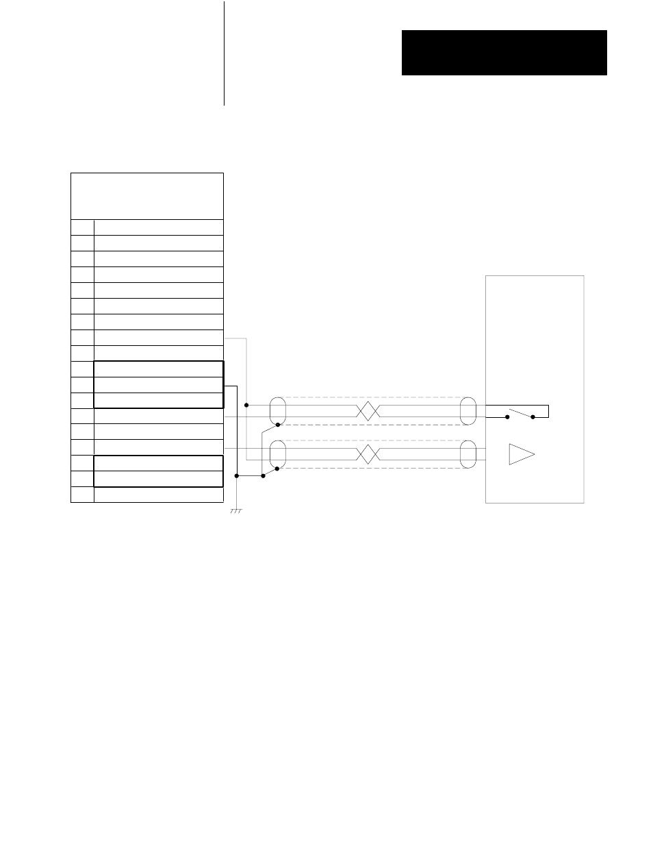
Figure 2.8
Control Mode Connections to Manual Control Station
18
INPUT 1 (+LEAD)
TERMINAL IDENTIFICATION
PID Module
CAT. NO. 1771-PDC
TERMINAL
FUNCTION
17
16
15
14
13
12
11
10
9
8
7
6
5
4
3
2
1
INPUT 1 (-LEAD)
INPUT 2 (+LEAD)
INPUT 2 (-LEAD)
TIEBACK INPUT 1
TIEBACK INPUT 2
ANALOG OUTPUT 1
MODULE COMMON
ANALOG OUTPUT 2
+ 15V DC
15V DC COMMON
- 15V DC
MANUAL MODE 1
MANUAL MODE 2
MANUAL REQUEST
OPT. +5V DC COMMON
OPTIONAL +5V DC
NOT USED
+-
General
Auto/Manual
Manual
11104
Manual Control
Station
Switch
Request
Input
The PID module is designed for use with commercially available manual
control stations, one per loop. The station is connected between the
analog output and the controlled element of the process. The station
provides manual override control and automatic backup to the PID
module. Manual control stations can be used for start-ups, on-line process
adjustments, and routine maintenance. The station can be used in either
of two ways, manual override control or module back-up.
Manual Override Control
An operator can override automatic control by switching to manual
control and adjusting the output at the manual control station. When the
manual control station is switched to manual mode, a connection is closed
between the MANUAL MODE terminal (referenced to +15V dc) and the
MODULE COMMON terminal on the PID module (Figure 2.8). This
Manual Control Station Interface