Rockwell Automation 1785-LTx,D17856.2.1 Classic PLC-5 Programmable Controllers Users Manual User Manual
Page 52
Assigning Addressing Modes,
Racks, and Groups
Chapter 4
4-10
When assigning rack numbers, use the following guidelines:
One I/O rack number is eight I/O groups, regardless of the addressing
mode that you select.
You can assign from one to four racks in your processor-resident
local chassis (128 inputs and 128 outputs) depending on the chassis
size and addressing mode. You cannot split a processor-resident local
I/O rack over two or more chassis or assign unused processor-resident
local I/O groups to remote I/O racks.
The default address of the processor-resident local rack is 0. You can
change the default to 1 by setting bit 2 in the processor control word
(S:26) on the processor configuration screen; you must also change the
mode of the processor from run to program to run.
An extended-local I/O and a remote I/O chassis cannot be addressed by
the same I/O rack number. For example, if an 8-slot extended-local I/O
chassis is configured as I/O groups 0-3 of I/O rack 2, an 8-slot remote
I/O chassis cannot be configured as I/O groups 4-7 of I/O rack 2.
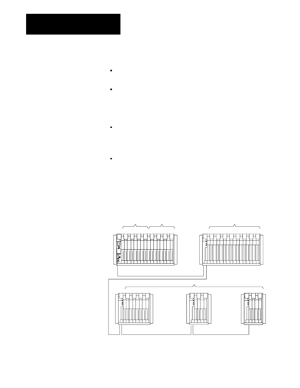
Remote I/O Racks
You can assign a remote I/O rack to a fraction of a chassis, a single I/O
chassis, or multiple I/O chassis:
I/O Rack No.0 I/O Rack No.1
01 23 45 67 01 23 45 67
0 1 2 3 4 5 6 7
I/O Rack No.2
0 1 2 3
4 5
6 7
I/O Rack No.3
16466
16Ćslot chassis, two racks
Power source not indicated
Power source not indicated
One
16Ćslot chassis, one rack
One
4Ćslot chassis, 1/2 rack
Power source not indicated
One
2Ćslot chassis, 1/4 rack each
Power source not indicated
Two