Chassis backplane with adapter module – Rockwell Automation 1785-LTx,D17856.2.1 Classic PLC-5 Programmable Controllers Users Manual User Manual
Page 140
Selecting Switch Settings
Appendix A
A-2
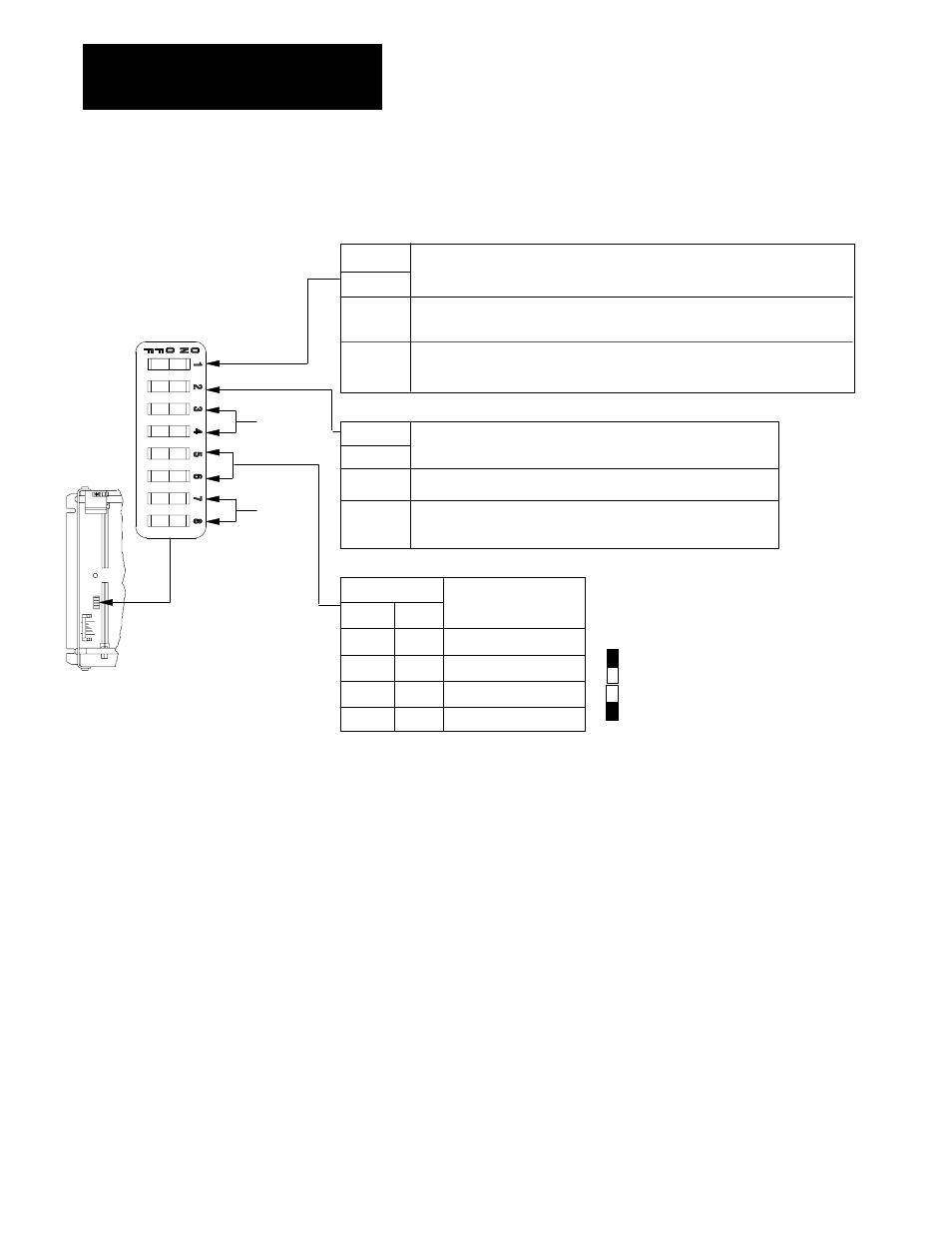
Make the following switch selections for a 1771-AS, -ASB, or -ALX
adapter module.
Switch
Switch
5
6
1
2
ON
OFF
Last State
Switches
Processor Restart Lockout
Addressing
Outputs of this I/O chassis remain in their last state when a communication fault is
detected by this I/O adapter.
1
Outputs of this I/O chassis are turned off when a comunication fault is detected
by this I/O adapter.
Processor can restart the I/O chassis after a communication fault.
2
You must manually restart the I/O chassis with a switch wired to the
1771ĆAS or ĆASB.
ON
ON
ON
ON
ON
OFF
OFF
OFF
OFF
OFF
2Ćslot
1Ćslot
3
1/2Ćslot
3
Not allowed
Pressed in at top Closed (ON)
Pressed in at bottom Open (OFF)
Always
Off
Always
Off
19308
1. ATTENTION: If you set this switch to the ON position, when a communication fault is detected, outputs connected to
this chassis remain in their last state to allow machine motion to continue. We recommed that you set switch 1 to
the OFF position to deĆenergize outputs wired to this chassis when a fault is detected.
Also, if outputs are controlled by inputs in a different rack and a remote I/O rack fault occurs (in the inputs rack), the
inputs are left in their last nonĆfaulted state. The outputs may not be properly controlled and potential personnel
and machine damage may result. If you want your inputs to be anything other than their last nonĆfaulted state,
then you need to program a fault routine.
2. Set this switch to ON if you plan to use I/O rack autoĆconfiguration.
3. The 1771ĆASB series A adapter does not support 1/2Ćslot addressing.
Chassis Backplane with
Adapter Module