Preface – Rockwell Automation 1785-LTx,D17856.2.1 Classic PLC-5 Programmable Controllers Users Manual User Manual
Page 10
Preface
v
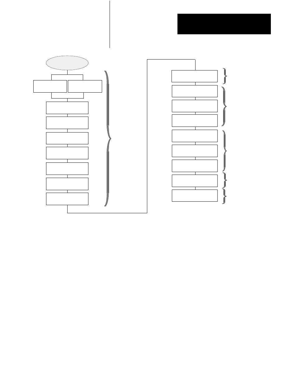
System Design
Determined
Select I/O
modules, terminals
Place
hardware
Select I/O chassis
Select power supply
Select PLCĆ5 processor
Select batteries and
memory modules
Complementary I/O
selected?
Backup system
selected?
Configure processor
communication
Configure Data
Highway Plus
Select programming
software
Data table layout and
processor status
Use fault routines
Choosing
Hardware
and
Placing
System
Hardware
Choosing
Communication
Assigning
Addressing Mode,
Racks, and Groups
I/O update and ladder
program scan times
Planning Your
System Programs
Calculating
Program Timing
and Maximizing
System
Performance
Transfer data in adapter
and scanner modes
Transferring
Discrete and
Block Data
Design SFCs
Select adapter modules
Assign
addressing
Since your decisions cannot always be made as a part of a strictly linear
process, you can choose to complete tasks in parallel. When you select
your I/O modules, for example, you can also begin to lay out and address
your modules. Consult chapter 3, “Placing System Hardware,” to
determine environmental requirements, enclosures needed, cable layout,
and grounding requirements for your chassis and I/O links. Also, you can
choose to assess block-transfer timing when you determine where you will
place your block-transfer modules (in the processor-resident local I/O
chassis, extended-local I/O chassis, or remote I/O chassis).