Rockwell Automation 1785-LTx,D17856.2.1 Classic PLC-5 Programmable Controllers Users Manual User Manual
Page 137
Chapter 10
Maximizing System Performance
10-5
However, if rack 2 has the most time-critical I/O, use the configurable scan
list to specify:
Using this scan list, rack 2 is scanned every other rack. There are 6 entries,
so the normal I/O scan time is 6 x 10 ms = 60 ms. Since rack 2 is scanned
every other rack, however, the rack 2 effective scan time is 2 x 10 ms =
20 ms. The remaining racks are scanned every 60ms. Thus, the tradeoff
for the more frequent scanning of rack 2 (every 20 ms) means that the
other racks are scanned only every 60 ms.
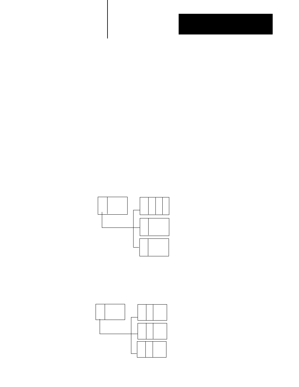
You can also optimize block transfers within the channel. You block
transfer to only one block transfer module per entry in the scan list per I/O
scan. If you have three block-transfer modules in one I/O rack, it takes a
minimum of three I/O scans to complete the block transfers to all of
the modules:
PLC
Adapter
BT BT BT
Adapter
Adapter
With this arrangement, there is only one block transfer
to each BT module for every 3 discrete I/O scans.
Maximum scan time
Minimum time to complete
a block transfer to all modules
= 3 discrete scans + 1 block transfer
= 3D + 1BT
= 3 * (3D + 1BT)
= 9D + 3BT
System Optimized for DiscreteĆData Transfer
If you place the three block-transfer modules in different racks, however,
you can block transfer to all three modules in one I/O scan. To optimize
your system layout for block-data transfers, use an arrangement similar
to the following:
PLC
Adapter
BT
BT
Adapter
Adapter
With this arrangement, there is a block transfer
to each BT module every discrete I/O scan.
Maximum scan time
Minimum time to complete
a block transfer to all modules
= 3 discrete scans + 3 block transfers
= 3D + 3BT
= 1 * (3D + 3BT)
= 3D + 3BT
BT
System Optimized for BlockĆData Transfer
rack 1
rack 2
rack 3
rack 4
rack 2
rack 2