Selecting i/o module density – Rockwell Automation 1785-LTx,D17856.2.1 Classic PLC-5 Programmable Controllers Users Manual User Manual
Page 21
Choosing Hardware
Chapter 2
2-2
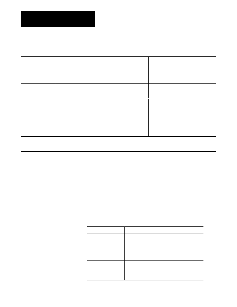
Table 2.A
Guidelines for Selecting I/O Modules
Choose this type of
I/O module:
For these types of field devices or operations (examples):
Explanation:
Discrete input module
and block I/O module
1
Selector switches, pushbuttons, photoelectric eyes, limit switches,
circuit breakers, proximity switches, level switches, motor starter
contacts, relay contacts, thumbwheel switches
Input modules sense ON/OFF or OPENED/
CLOSED signals. Discrete signals can be either
ac or dc.
Discrete output module
and block I/O module
1
Alarms, control relays, fans, lights, horns, valves, motor
starters, solenoids
Output module signals interface with ON/OFF or
OPENED/CLOSED devices. Discrete signals can
be either ac or dc.
Analog input module
Temperature transducers, pressure transducers, load cell transducers,
humidity transducers, flow transducers, potentiometers
Convert continuous analog signals into input
values for PLC processor.
Analog output module
Analog valves, actuators, chart recorders, electric motor drives,
analog meters
Interpret PLC processor output to analog signals
(generally through transducers) for field devices.
Specialty I/O modules
Encoders, flow meters, I/O communication, ASCII, RF type devices,
weigh scales, barĆcode readers, tag readers, display devices
Are generally used for specific applications such
as position control, PID, and external device
communication.
1
A 1791 block I/O module is a remote I/O device that has a power supply, remote I/O adapter, signal conditioning circuitry, and I/O
connections. A block I/O module does not require a chassis mount. It is used to control concentrated discrete remote I/O such as control
panels, pilot lights, and status indications.
Important: Determine addressing in conjunction with I/O module
selection. The selection of addressing and the selection of I/O module
density are mutually dependent.
Selecting I/O Module Density
The density of an I/O module is the number of processor input or output
image table bits to which it corresponds. A bidirectional module with 8
input bits and 8 output bits has a density of 8. Table 2.B provides
guidelines for selecting I/O module density.
Table 2.B
Guidelines for Selecting I/O Module Density
Choose this I/O density: If you:
8Ćpoint I/O module
•
currently use 8Ćpoint modules
•
need integral, separatelyĆfused outputs
•
want to minimize cost per module
16Ćpoint I/O module
•
currently use 16Ćpoint modules
•
need separately fused outputs with a special wiring arm
32Ćpoint I/O module
•
currently use 32Ćpoint modules
•
want to minimize number of modules
•
want to minimize the space required for I/O chassis
•
want to minimize cost per I/O point