Axis program – Rockwell Automation 1771-QA Stepper Positioning Assembly User Manual User Manual
Page 93
4–15
Example Programs
Publication 1771-UM002A–EN–P – May 2000
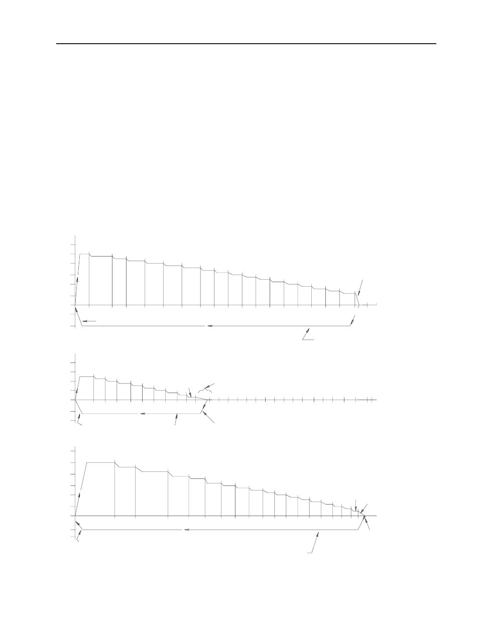
The ladder diagram program presented in this section is written for a
3-axis machine operation where each axis has a different 20-move
continuous mode positioning profile. Sketches of the three profiles
are shown in Figure 4.6. A detailed profile for each axis is shown in
Figure 4.7, Figure 4.8 and Figure 4.9.
The 3-axis system requires that one Stepper Controller Module (cat.
no. 1771-M1) and three Pulse Output Expander Modules (cat. no.
1771-OJ) be used in the same I/O chassis.
The operational functions and hardware input options are generally
the same as the 1-axis program described in section 4.1. It is
assumed that an industrial terminal and either a Mini-PLC-2/15 or
PLC-2/30 programmable controller are being used.
Figure 4.6
Example 3-Axis Profile (Continuous Mode)
Axis #1
18
Move 19
RT=3.0 Sec
Move 20
RT=3.0 Sec
1k 2k 3k 4k
5k 6k
7k 8k 9k
10k 11k 12k 13k 14k 15k 16k 17k 18k
1200
1000
800
600
400
200
0
–1K
–2K
8
9
10
11
12
13
14
RT=2.0 Sec
1k 2k
13k
3k
4k
5k
16
7k
6k
8k
Move 20
RT=2.0 Sec
Moves 11–19
12k
Axis #2
Axis #3
22k 23k
1
2
3
4
5
6
7
RT=2.0 Sec
1k2k3k 4k 5k 6k 7k 8k 9k 10k 11k
Move 20
RT=2.0 Sec
19
Move 18
1
2
3
4
5
6
7
8
9
10 11 12 13 14 15
17
16
15
10620
17
800
600
400
200
0
–1K
–2K
1200
1000
800
600
400
200
0
–1K
–2K
19k 20k 21k
Move 2-18 Ramp Time = 1.0 Sec
Move 19 is a 0 Hz Rate Move
8
9
10
1
2
3
4
5
6
7
14k 15k 16k 17k 18k
22k
23k
19k 20k
21k
Move 2-18 Ramp Time = 1.0 Sec
Move 19 is a 0 Hz Rate Move
Move 2-18 Ramp Time = 1.0 Sec
Move 19 is a 0 Hz Rate Move
3-Axis Program