Assembly and installation, Chapter, General input considerations – Rockwell Automation 1771-QA Stepper Positioning Assembly User Manual User Manual
Page 11
Chapter
2
Publication 1771-UM002A–EN–P – May 2000
Assembly and Installation
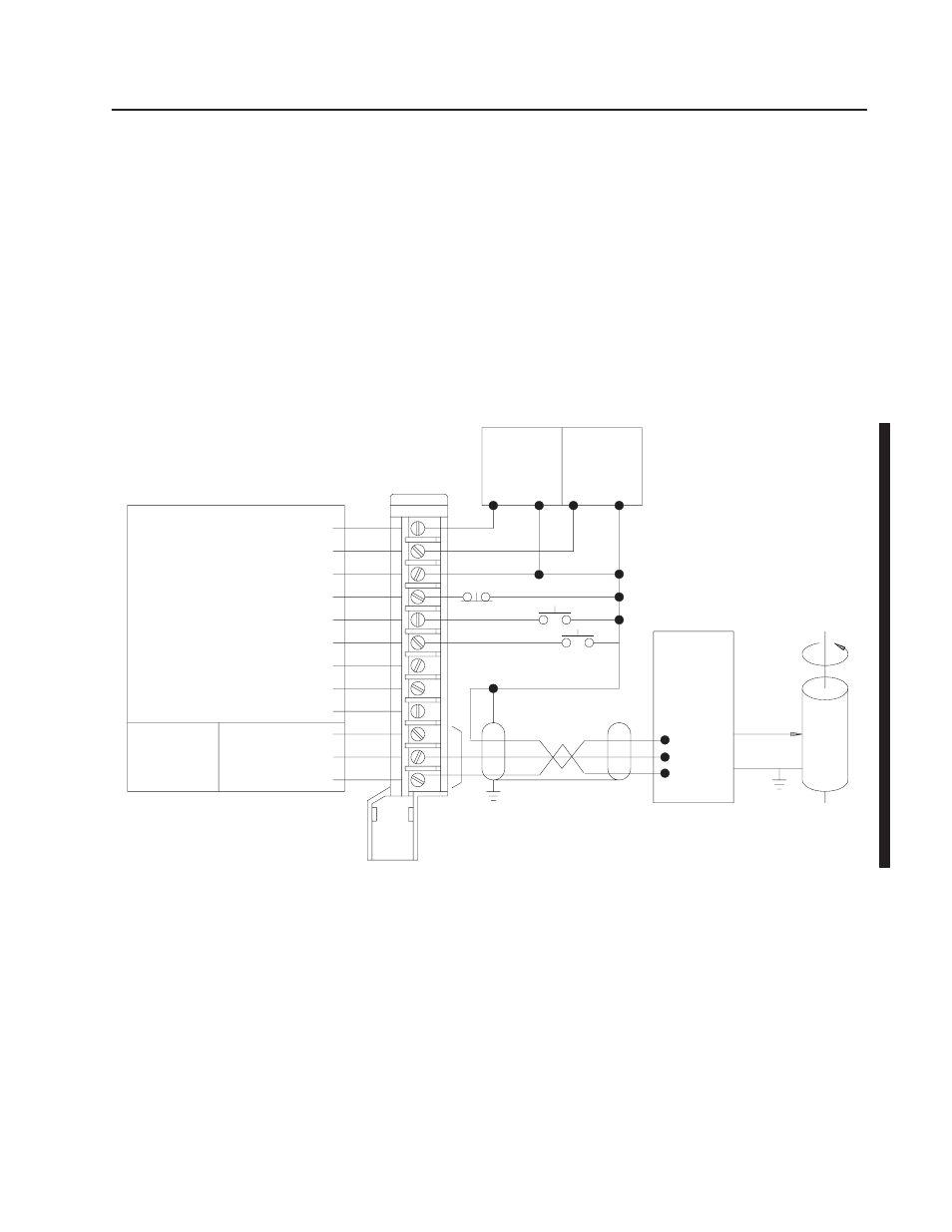
The stepper positioning assembly can be wired for 1-axis operation
with a stepper translator and motor as shown in Figure 2.1. One
stepper controller module can control up to three pulse output
expander modules installed in the same chassis. When the
application calls for 2-or 3-axis control, each additional expander
module should be wired as shown in Figure 2.1. No more than one
stepper controller module can operate in an I/O chassis.
Figure 2.1
Typical 1-Axis Connection Diagram
+ DC Input Supply
10510
Output
Stepper
Pulse Output
Input
Mechanical
Stepper
Rate Pulses/
+ DC Output Supply
Common
Stop Input
Jog Forward Input
Jog Reverse Input
Not Used
Not Used
Not Used
Rate
Fwd Dir
Rev Dir
Rev Rate
Fwd Rate
Not Used
Motor
Load
Translator
and
Power
Supply
+
–
+
–
Expander Module
Field Wiring Arm
1771–WB
Directional Signals
1
2
3
4
5
6
7
8
9
10
11
12
NEC Class 2
Power
Supply
NEC Class 2
Power
Supply
Pulse output expander modules can be controlled manually by the
use of switch inputs for stop, jog forward and jog reverse. The stop
switch will cause output pulses to the corresponding axis to cease
instantaneously. Jog switches are operational only when the
corresponding axis is at rest.
General
Input Considerations