Rockwell Automation 1771-QA Stepper Positioning Assembly User Manual User Manual
Page 39
3–17
Programming and Operation
Publication 1771-UM002A–EN–P – May 2000
Move Block
A move block contains ramp, final rate, final position and
deceleration data that characterize a move. A moveset block must
contain from 1 to 10 move blocks. A move block contains the
following words (Figure 3.12):
•
Single Move Control Word
•
Move Data
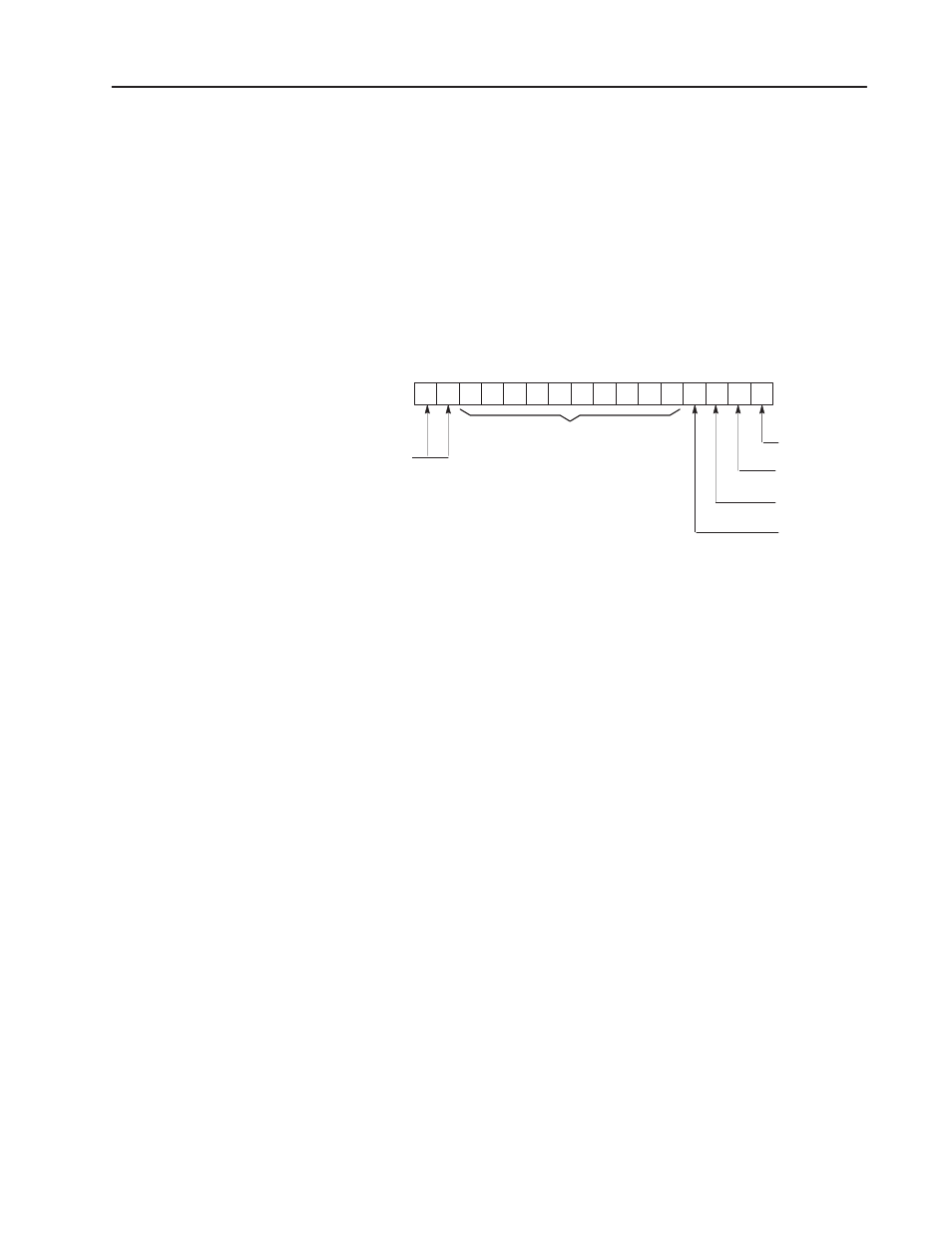
Figure 3.12
Single Move Control Word
17 16
SMCW
03 02 01 00
Move Preset
Rate Multiplier
Move Skip
Load Jog
Always 1 to
10526
identify the SMCW
1
1
0
0
0
0
0
0
0
0
0
0
Always Zero
Single Move Control Word
The single move control word is the first word in each move block.
The word contains two identification bits (bits 16, 17) and four bits
which affect the operation of the move (bits 00-03). The function of
each bit is defined below and summarized in Figure 3.12.
Bit 00 Move Preset Bit.
This bit, when set, causes the value contained in the preset words of
the moveset block to become the starting point value for that move.
The position register becomes this value. The preset value can be
changed and re-enabled as needed to further extend the position limit
or to allow the profile to return to the home position. Refer to
“Move Preset.”
Bit 01 Rate Multiplier Bit.
When the rate multiplier bit is set, final rates can be selected in 10
pulses per second increments between 0 and 20,000 pulses per
second.
When this bit is zero, any final rate from 1 to 9,999 pulses per
second can be selected in 1 pulse per second increments.
This bit would typically be set when ramp, rate and decel values are
initially set in the data table using the data monitor mode of the
industrial terminal.