Moveset control word – Rockwell Automation 1771-QA Stepper Positioning Assembly User Manual User Manual
Page 31
3–9
Programming and Operation
Publication 1771-UM002A–EN–P – May 2000
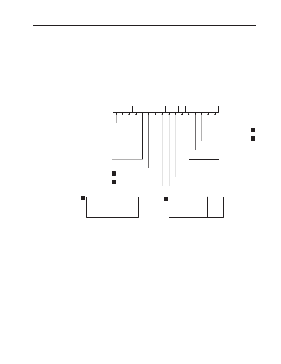
Moveset Control Word
A moveset block must contain a moveset control word as the first
word in the block. Each of the bits of the moveset control word
serves a function in the control of a stepper motor axis. Bit functions
of the moveset control word are defined below and summarized in
Figure 3.7.
Figure 3.7
Moveset Control Word
17 16 15 14 13 12 11 10 07 06 05 04 03 02 01 00
MCW
Start
Profile Mode Select
Profile Mode Select
Synchronized Axes
Reset
Global/Axis
Stop
Decel/Instantaneous
10520
Override
Moveset
Jog Forward
Jog Reverse
Offset
Not Used (Must be zero)
Axis Address
Axis Address
Axis Addr.
1
2
3
Bit 11
0
1
1
1
0
1
Bit 10
Mode
Continuous
Independent
Single Step
Bit 02
0
1
N/A
0
0
1
Bit 01
2
1
1
2
2
1
Bit 00 Start Command Bit.
When this bit is set, the stepper controller module will start to
execute the first move of a continuous or independent mode
sequence or the next single step move.
Bit 01, 02 Mode Select Bits.
These two bits are used to determine the type of positioning profile.
Bit 01=0, Bit 02=0: Continuous Mode (Figure 3.3)
Bit 01=0, Bit 02=1: Independent Mode (Figure 3.4)
Bit 01=1, Bit 02=1 or 0: Single-Step Mode (Figure 3.2)
Refer to section titled “Positioning Modes” for mode descriptions.