Rockwell Automation 1771-QA Stepper Positioning Assembly User Manual User Manual
Page 48
3–26
Programming and Operation
Publication 1771-UM002A–EN–P – May 2000
The data address of a block transfer instruction should be the first
available address in the timer/counter accumulated area of the data
table. This address is 030
8
for the Mini-PLC-2/15 controller. For
the PLC-2/30 controller, this address depends on the number of I/O
racks connected to the processor module, i.e. address 020
8
for one
I/O rack, 030
8
for two racks, etc. to 070
8
for six racks and 200
8
for
seven racks. When more than one block transfer module is used, the
data addresses should be consecutive.
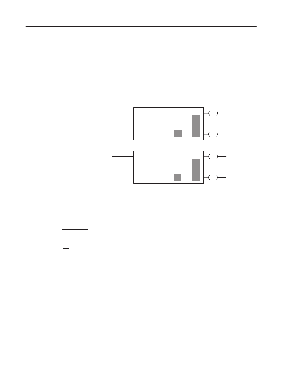
Figure 3.16
Block Transfer Instruction Format
BLOCK XFER READ
DATA ADDR
MODULE ADDR
BLOCK LENGTH
FILE
110
110
01
100
030
EN
110
010
07
07
–
DN
BLOCK XFER WRITE
DATA ADDR
MODULE ADDR
BLOCK LENGTH
FILE
110
110
01
100
030
EN
110
010
06
06
–
DN
Numbers shown are default values. Numbers in shaded areas must be replacced by uer-entered values. The number of default
address digits initially displayed, 3, 4, or 5 will depend on the size of the data table. Initially displayed default values are governed
by the I/O rack configuration.
Data Address:
Module address:
Block Length:
File:
Enable Bit–( EN )–:
Done Bit –( DN )–:
First possible address in accumulated value area of data table.
Rack module group and slot number.
Number of words to be transferred (00 can be entered for default value or for 64 words.)
Automatically entered from the module address. Set to 1 when rung containing the instruction is true.
Automatically entered from the module address. Remains set to one scan following successful transfer.
10224
Address of first word of file. Storage locations 100
8
above the data address.