Rockwell Automation 1771-QA Stepper Positioning Assembly User Manual User Manual
Page 17
2–7
Assembly and Installation
Publication 1771-UM002A–EN–P – May 2000
Table 2.D
Expander Module Address (S3)
Switch Assembly S3
Expander
Switch 1
Switch 2
Switch 3
Address
ON
OFF
OFF
1
OFF
ON
OFF
2
ON
ON
OFF
3
Expander Module Output (S4, S5, S6)
The choice of pulse output expander module output, either push-pull,
current source (open emitter) or current sink (open collector), is
user-selectable to best match the input characteristics of the stepper
translator.
PUSH-PULL-OPEN The push-pull output is compatible with many
stepper translators. The expander module output is wired to the
translator input as shown in Figure 2.1.
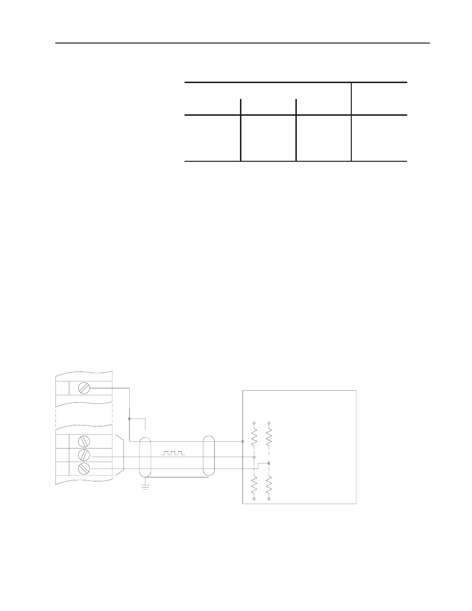
CURRENT SOURCE or CURRENT SINK-OPEN When using the
expander module as a current source or sink for the output pulses, it
may be necessary to use a pull-down or pull-up resistor, respectively
(Figure 2.3) Refer to the translator input specifications and
installation instructions for correct use of this resistor if it is required.
Figure 2.3
Output Source or Sink Connections
Common
Direction
+Supply
Pull–Up
–Supply
Translator
Expander Module
12
11
10
3
10512
Resistors
(Current Sink)
or
Pull–Down
Resistors
(Current Source)
The positive (+) and negative (-) terminals of the output power
supply must be connected to the + DC OUTPUT SUPPLY and
COMMON terminals, respectively, of the module field wiring arm
regardless of the choice of module output.