Rockwell Automation 1771-QA Stepper Positioning Assembly User Manual User Manual
Page 122
F
F
5–2
Troubleshooting
Publication 1771-UM002A–EN–P – May 2000
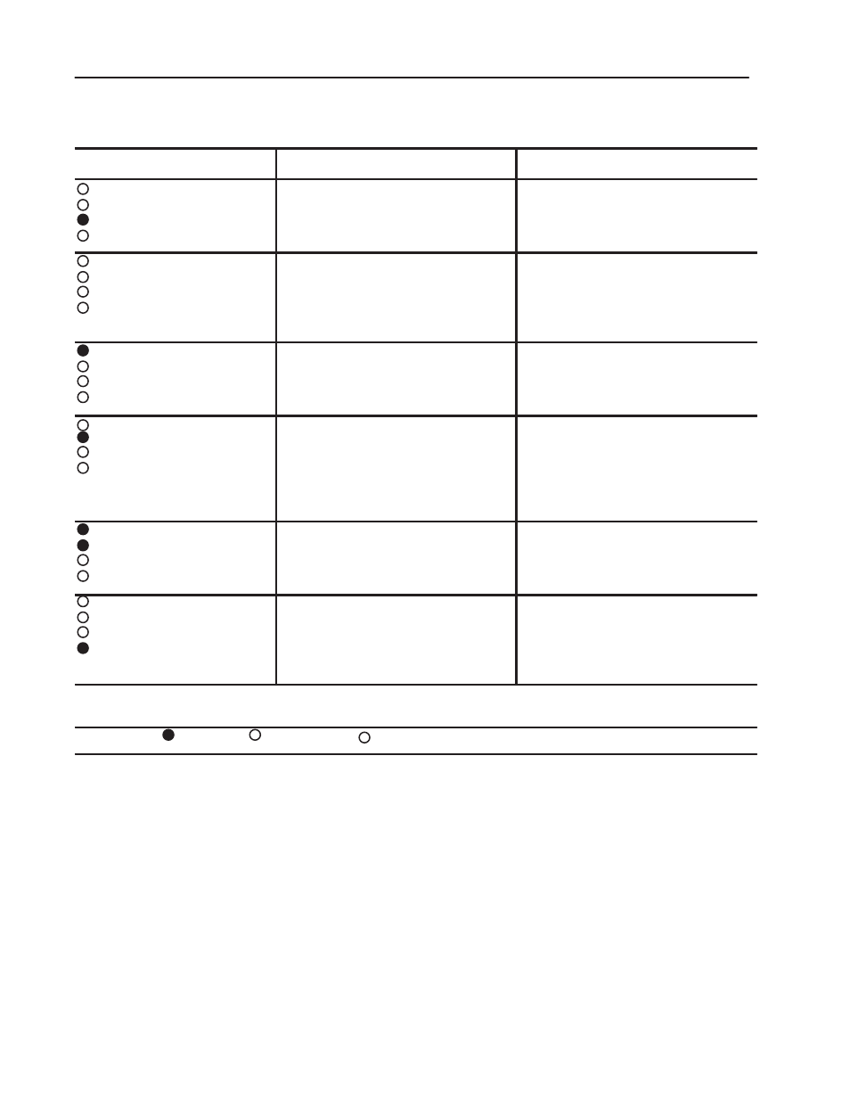
Table 5.A
Power-Up Troubleshooting
Led Indication
Possible Cause
Corrective Action
PC COMM FAULT
1
EXPANDER COMM FAULT
1
ACTIVE
1
MODULE FAULT
2
Normal Operation
None
PC COMM FAULT
EXPANDER COMM FAULT
ACTIVE
MODULE FAULT
Expander address is incorrect.
More than one 1771-M1 module in the
chassis
No 1771-OJ module in the chassis
Switch 3 on 1771-OJ module must be 001,
010 or 011.
Install only one 1771-M1 module per chassis.
Install at least one 1771-OJ module per
chassis.
PC COMM FAULT
EXPANDER COMM FAULT
ACTIVE
MODULE FAULT
Block transfer error
Check cables and adapters for faulty or
intermittent operation.
Check for invalid block transfer starting
address.
PC COMM FAULT
EXPANDER COMM FAULT
ACTIVE
MODULE FAULT
Communications error between 1771-M1
module and 1771-OJ
Check that all modules are properly installed
in chassis.
Noisy environment: check earth grounding of
chassis power supplies, stepper
motor/translator and noise sources (relays,
motors, etc.) too close to the chassis.
PC COMM FAULT
EXPANDER COMM FAULT
ACTIVE
MODULE FAULT
Hardware failure
Cycle power to chassis.
If problem still exists, replace module.
PC COMM FAULT
EXPANDER COMM FAULT
ACTIVE
MODULE FAULT
Communications error between 1771-M1 and
1771-OJ modules
Initialization error
Watchdog timers timed-out
See CORRECTIVE ACTION above for
Comm. Error between 1771-M1 and 1771-OJ
modules.
Hardware error, see above
Hardware error, see above
1
LED indicators on the stepper controller module
2
LED indicator on the pulse output expander module
Legend: ON OFF Flashing