Specifications, Appendix – Rockwell Automation 1771-QA Stepper Positioning Assembly User Manual User Manual
Page 127
Appendix
A
Publication 1771-UM002A–EN–P – May 2000
Specifications
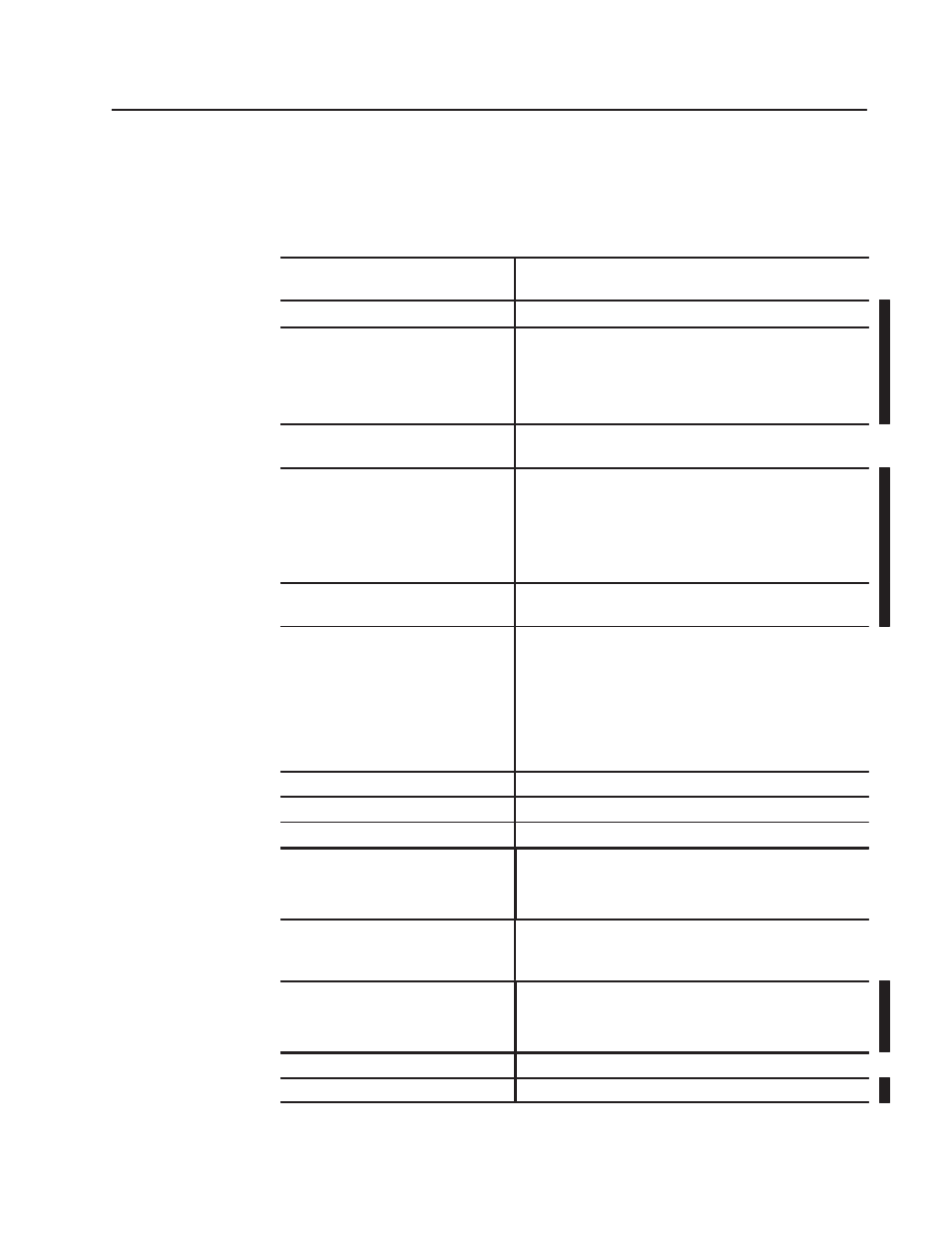
Pulse Output Expander Module Specifications (cat. no. 1771-OJ)
Module Location
Bulletin 1771 I/O Rack
1 module slot, not address dependent
Backplane Power Requirements
800mA, 5V dc
Auxiliary Power Supply Requirements (V+)
NEC Class 2 listed
+5 to +30V DC
340mA max.
Ripple: Not to exceed the input specification for the stepper
translator
Input Delay
JOG: 35ms (1-axis) thru 120ms (3-axis)
STOP: 250 microseconds
Input Voltage Range
Minimum High State: +V supply -1.0 volts.
The module has a 1.6k ohm internal pull-up resistor.
Therefore:
1) Open collector logic devices are compatible
2) Hard contacts need only be opened (or floated).
Maximum Low State: 0.8V DC
On-State Current per Input
5V: 1.0mA typical, 2.3mA max.
30V: 12.6mA typical, 18.6mA max.
Output Voltage Range
When Output Current = 100mA
•
Minimum High State Voltage: (+V supply -2.6) V typical, (+V
supply -4.2) V worst case
•
Maximum Low State Voltage: +.7V typical, +1.0V worse case
When Output Current = 10mA
•
Minimum High State Voltage (+V supply -1.4) V typical, (+V
supply, 1.8) V worst case
•
Maximum Low State Voltage: +.25V typical, +.40V worst case
Maximum Output Current
100mA
Worst Case rise/fall time (@100mA)
0.6 microseconds
Duty Cycle of Pulses
50%
Environmental Conditions
Operational Temperature
Storage Temperature
Relative Humidity
0
o
to 60
o
C (32
o
to 140
o
F)
-40
o
to 85
o
C (-40
o
to 185
o
F)
5 to 95% (without condensation)
Keying
Insert keying bands between:
8 and 10 and
22 and 24
Wire Type and Range
Type
Range
Restrictions
Category
Belden 8771,
40ft maximum,
use stranded copper wire only, 1 wire per terminal
Category 2
1
Wiring Arm
Catalog Number 1771-WN
Wiring Arm Screw Torque
9 pound-inches (1.0Nm)