Rockwell Automation 1771-QA Stepper Positioning Assembly User Manual User Manual
Page 44
3–22
Programming and Operation
Publication 1771-UM002A–EN–P – May 2000
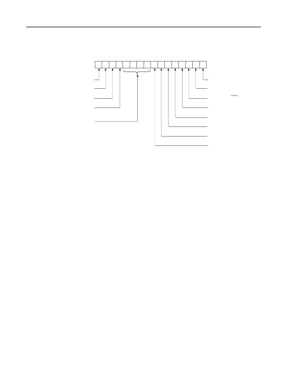
Figure 3.15
Status Word
17 16 15 14 13 12 11 10 07 06 05 04 03 02 01 00
Status word
Command Verified
Data Received
Direction Rev/Fwd
System Fault
Programming Error
Reset
Program Stop
Hardware Stop
Done
Moveset
Jog Forward
Jog Reverse
Move Number 1 – 10
10520
(1-A Hex)
Status Word
The bits in the status word allow the PC program to verify that move
commands have been received and implemented. The bits can be
monitored visually or used to display which portion of the
positioning profile is currently in operation, the status of the current
move and the nature of any fault or error detected by the stepper
controller module. The functions of the status word bits are defined
below and summarized in Figure 3.15.
Status Bits
Except as noted below, the status bits verify that a particular
command has been received by the stepper controller module.
Bit 00 Command Verify Bit.
This bit is set to verify that a command bit (start, stop, offset, jog
reverse, jog forward, override, initialization preset or load jog) has
been received.
Bit 01 Data Received Bit.
This bit toggles alternately to 0 or 1 every time a new write block
transfer is received.
Bit 02 Direction Bit.
This bit indicates the direction of rotation, 0 for forward or 1 for
reverse.