Drive 0 control routines, Main routine – Rockwell Automation 25-COMM-P PowerFlex PROFIBUS DPV1 Adapter User Manual
Page 62
62
Rockwell Automation Publication 520COM-UM004A-EN-E - November 2013
Chapter 7
Using Multi-Drive Mode
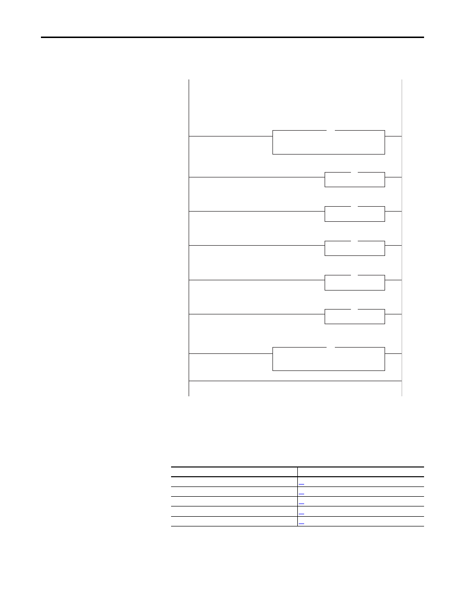
Main Routine
Drive 0...4 Control Routines
The following Drive Control routines provide status information (Logic Status
and Feedback) and control (Logic Command and Reference):
Control Routine
See page...
Drive 0
Drive 1
Drive 2
Drive 3
Drive 4
0
1
2
3
4
5
6
(End)
Copy File
Source
Dest
Length
MVI69PDPMV1.Input[0]
Drive_Input_Image[0]
10
Jump To Subroutine
Routine Name Drive0
JSR
COP
Copy File
Source
Dest
Length
Drive_Output_Image[0]
MVI69PDPMV1.Output[0]
10
COP
Jump To Subroutine
Routine Name Drive1
JSR
Jump To Subroutine
Routine Name Drive2
JSR
Jump To Subroutine
Routine Name Drive3
JSR
Jump To Subroutine
Routine Name Drive4
JSR
Drive 0 control subroutine.
Drive 1 control subroutine.
Drive 2 control subroutine.
Drive 3 control subroutine.
Drive 4 control subroutine.
CompactLogix Multi-Drive example program with a PowerFlex 525 on PROFIBUS DP.
Four PowerFlex 4M drives are daisy-chained to the main PowerFlex 525 using their RJ45 ports (RS-485). In this mode,
up to five PowerFlex drives can exist on one PROFIBUS DP node.
This rung retrieves the Logic Status and Feedback data for all five drives from the master, and moves it to
specific INT tags for use elsewhere in the ladder program. The input image is as follows:
This rung writes the output image to the master. The output image is as follows:
PowerFlex 525 PROFIBUS DP Multi-Drive Demo