Setting the endianness and – Rockwell Automation 25-COMM-P PowerFlex PROFIBUS DPV1 Adapter User Manual
Page 14
14
Rockwell Automation Publication 520COM-UM004A-EN-E - November 2013
Chapter 2
Installing the Adapter
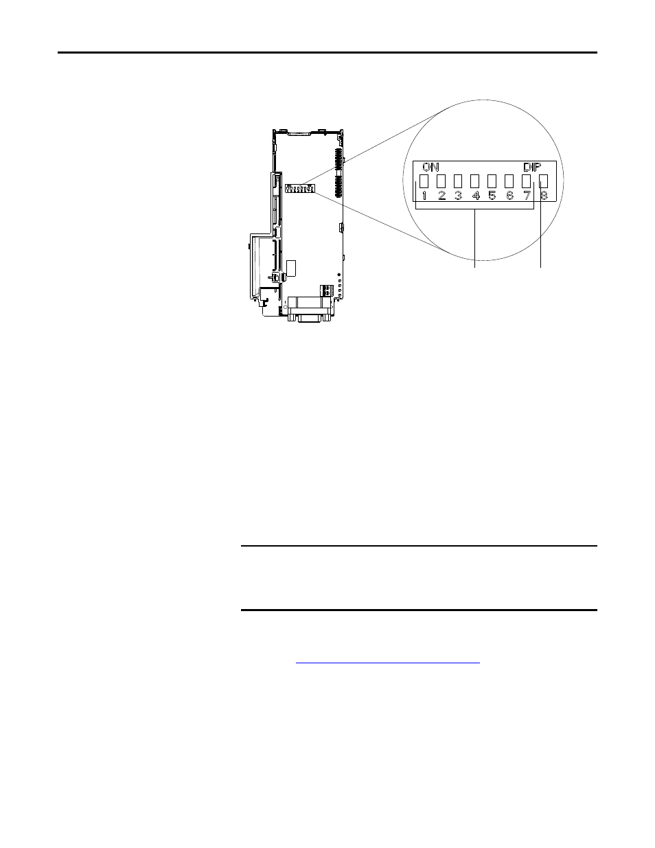
Setting the Endianness and Node Address Using the DIP Switches
Set the Endianness of the adapter with Byte Swap switch 8. The Byte Swap switch
can be set to either OFF ‘0’ (Little Endian) or ON ‘1’ (Big Endian) data formats
for the data exchanged on the network. The data consists of the following items:
•
CTRL: Logic Command Word (four bytes)
•
REF: Speed Reference (two bytes)
•
STAT: Logic Status Word (four bytes)
•
FEEDBACK: Speed Feedback (two bytes)
•
zero to eight Datalinks (two bytes each)
•
Acyclic messaging
Depending on the setting of the Byte Swap switch 8, the two bytes for each of the
above data items are swapped.
Set the Node Address by setting the Node Address switches 1 through 7 to their
binary equivalent, where ‘0’ and ‘1’ indicate switch positions ‘OFF’ and ‘ON’
respectively.
Node Address Switch Settings on page 15
lists node addresses and
the corresponding Node Address switch settings required to set that respective
address.
IMPORTANT
Each node on the PROFIBUS network must have a unique address. Set the node
address before power is applied because the adapter detects the node address
during initialization (Power On Reset). Unless using the Set Slave Address
service in which the address change occurs without requiring a power cycle.
Node Address
switches (1...7)
Byte Swap
switch (8)