Understanding the i/o image, Using logic command/status, Using reference/feedback – Rockwell Automation 25-COMM-P PowerFlex PROFIBUS DPV1 Adapter User Manual
Page 42
42
Rockwell Automation Publication 520COM-UM004A-EN-E - November 2013
Chapter 5
Using the I/O
Understanding the I/O Image
The terms
input and output are defined from the controller’s point of view.
Therefore, output I/O is data that is produced by the controller and consumed by
the adapter. Input I/O is status data that is produced by the adapter and
consumed as input by the controller. The I/O image will vary based on how many
of the drive’s 16-bit Datalinks (
Host parameters C161...C164 [Opt Data In
1...4]
and C165...C168 [Opt Data Out 1...4]) are used.
If all available I/O is not used, the image is truncated. The image always uses
consecutive words starting at word zero.
CompactLogix Controller I/O Image for PowerFlex 520-Series Drives on
page 42
shows the I/O image when using all of the 16-bit Datalinks.
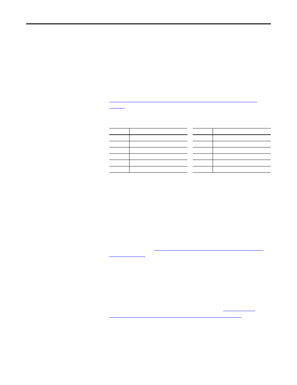
CompactLogix Controller I/O Image for PowerFlex 520-Series Drives
Using Logic Command/Status
The Logic Command is a 16-bit word of control data produced by the controller
and consumed by the adapter. The Logic Status is a 16-bit word of status data
produced by the adapter and consumed by the controller.
When using a CompactLogix or ControlLogix controller, the Logic Command
word is always INT 0 in the output image and the Logic Status word is always
INT 0 in the input image.
This manual contains the bit definitions for compatible products available at the
time of publication in
Logic Command/Status Words: PowerFlex 520-Series
Using Reference/Feedback
The Reference is a 16-bit INT (integer) produced by the controller and
consumed by the adapter. The Feedback is a 16-bit INT produced by the adapter
and consumed by the controller.
When using a CompactLogix or ControlLogix controller, the 16-bit INT
Reference word is always INT 1 in the output image (see
Controller I/O Image for PowerFlex 520-Series Drives on page 42
) and the
16-bit INT Feedback is always INT 1 in the input image.
The Reference and Feedback 16-bit INT values represent drive speed. The
scaling for the speed Reference and Feedback is 0.01 Hz. For example, a 16-bit
INT Reference value of ‘3000’ would equal a Reference of 30.00 Hz. Note that
the commanded maximum speed can never exceed the value of
Host parameter
(16-bit Logic Command/Status, Reference/Feedback, and Datalinks)
INT
Output I/O
INT
Input I/O
0
Logic Command
0
Logic Status
1
Reference
1
Feedback
2
Datalink 1
2
Datalink 1
3
Datalink 2
3
Datalink 2
4
Datalink 3
4
Datalink 3
5
Datalink 4
5
Datalink 4