Compactlogix controller example, Main routine – Rockwell Automation 25-COMM-P PowerFlex PROFIBUS DPV1 Adapter User Manual
Page 61
Rockwell Automation Publication 520COM-UM004A-EN-E - November 2013
61
Using Multi-Drive Mode
Chapter 7
CompactLogix Controller
Example
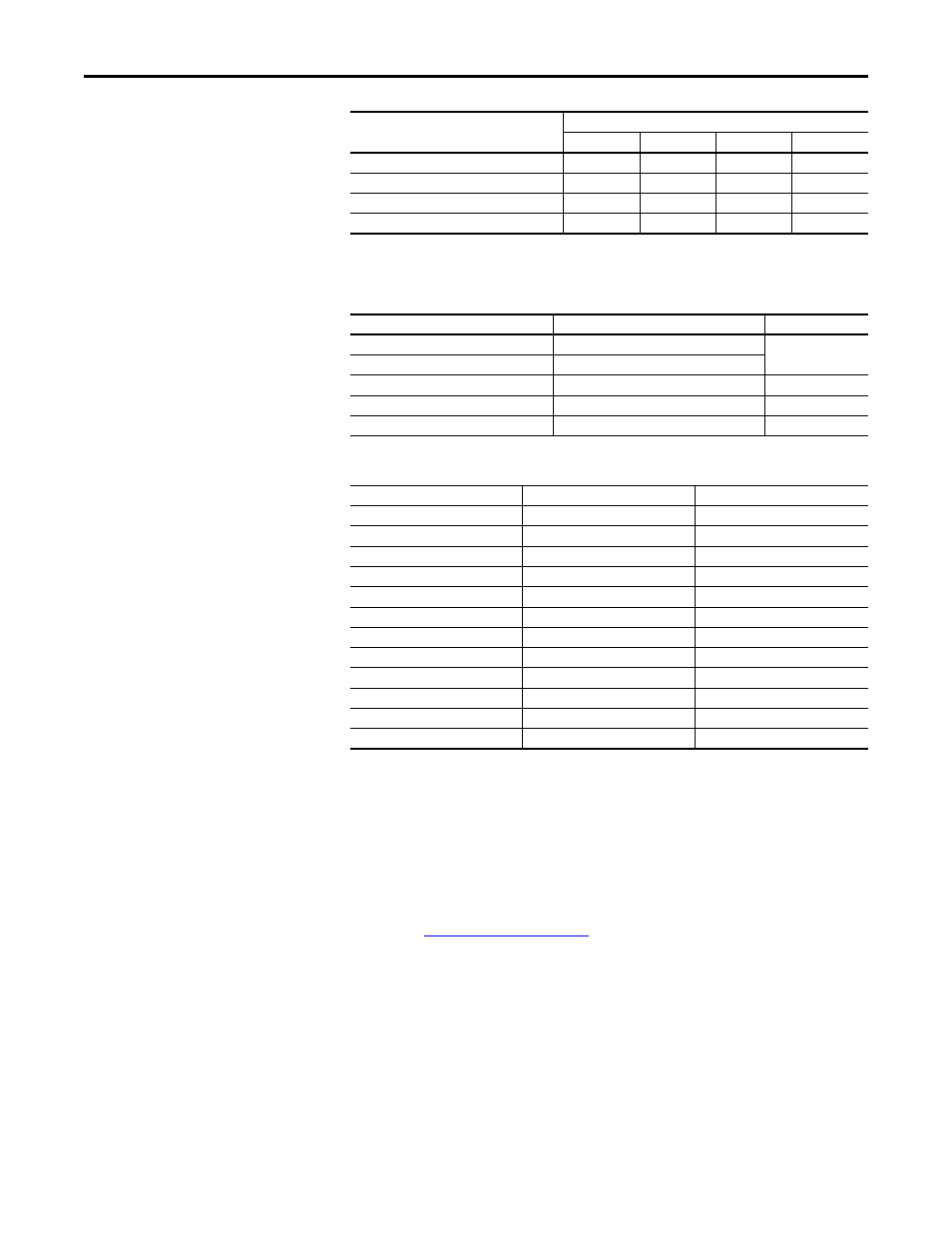
The following common Tags are used:
The following Tags are used for Drive 0:
The same type of Tags are also used for Drive 1 through Drive 4.
Main Routine
The Main Routine reads the network Input Image from the master, calls the
various drive control subroutines, and writes the network Output Image to the
master. See
C303 [Comm Node Addr]
1
2
3
4
C304 [Comm Loss Action]
0
0
0
0
C305 [Comm Loss Time]
5.0 s
5.0 s
5.0 s
5.0 s
C306 [Comm Format]
0
0
0
0
Value
Parameter
Drive 1
Drive 2
Drive 3
Drive 4
Tag Name
Type
Description
MVI69PDPMV1.Input
INT [62]
Created by ProSoft
AOP
MVI69PDPMV1.Output
INT [61]
Accel_Time_1
INT
–
Drive_Input_Image
INT [10]
Input Image Table
Drive_Output_Image
INT [10]
Output Image Table
Tag Name
Type
Description
Drive_0_Command_Stop
BOOL
Logic Command bit 0 (STOP)
Drive_0_Command_Start
BOOL
Logic Command bit 1 (START)
Drive_0_Command_Jog
BOOL
Logic Command bit 2 (JOG)
Drive_0_Command_Clear_Faults
BOOL
Logic Command bit 3 (CLEAR FAULTS)
Drive_0_Command_Forward
BOOL
Logic Command bit 4 (FORWARD)
Drive_0_Reference
INT
Speed Reference
Drive_0_Status_Ready
BOOL
Logic Status bit 0 (READY)
Drive_0_Status_Active
BOOL
Logic Status bit 1 (ACTIVE)
Drive_0_Status_Forward
BOOL
Logic Status bit 2 (FORWARD)
Drive_0_Status_Faulted
BOOL
Logic Status bit 7 (FAULT)
Drive_0_Status_At_Reference
BOOL
Logic Status bit 8 (AT SPEED)
Drive_0_Feedback
INT
Speed Feedback