Network termination, Applying power, Start-up status indication – Rockwell Automation 25-COMM-P PowerFlex PROFIBUS DPV1 Adapter User Manual
Page 20: Network termination applying power
20
Rockwell Automation Publication 520COM-UM004A-EN-E - November 2013
Chapter 2
Installing the Adapter
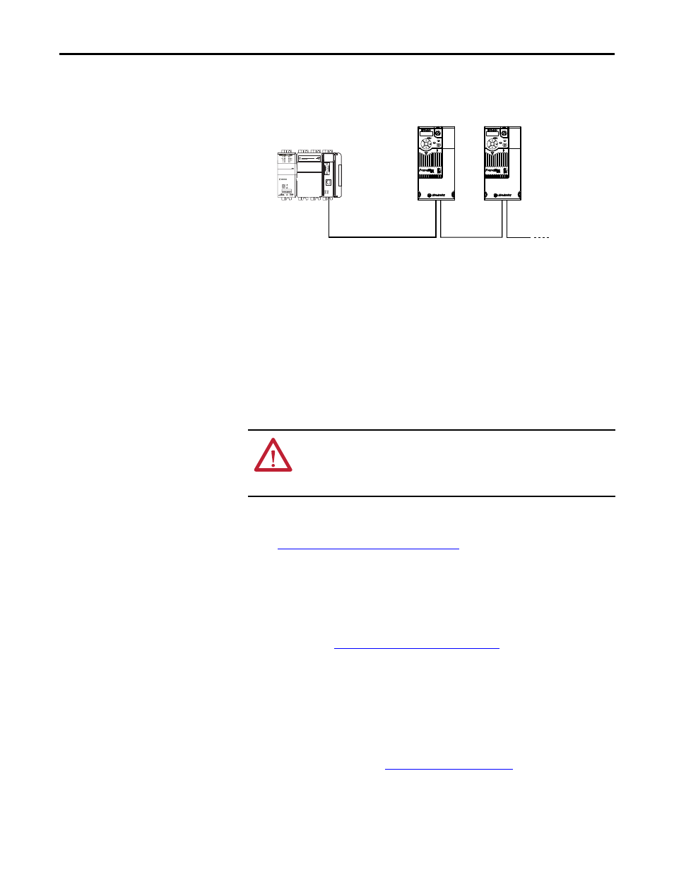
Wiring Example
6.
Connect the other end of the PROFIBUS cable to the PROFIBUS
network.
Network Termination
The first and last node on a PROFIBUS DP Network segment should be
terminated.
Rockwell Automation recommends that the user select one of the
aforementioned PROFIBUS connectors with built-in termination.
Applying Power
1.
Make sure that the adapter will have a unique address on the network and
Endianness is set. If a new address is needed, reset its switches (see
Commissioning the Adapter on page 13
).
2.
Apply power to the drive. The adapter receives its power from the
connected drive.
3.
If the parameter settings for the Endianness and node address are to be
used, a configuration tool such as Connected Components Workbench
(version 3 or greater) can be used to adjust the respective parameters in the
adapter. See
Configuring the Adapter on page 23
.
Start-Up Status Indication
After power has been applied, the status indicators can be viewed on the front of
the drive. When you apply power to the product and network for the first time,
the status indicators should be green after an initialization. If the status indicators
go red, there is a problem. See
.
Esc
Sel
Esc
Sel
PROFIBUS
PROFIBUS network
PowerFlex 525
with 25-COMM-P
PowerFlex 525
with 25-COMM-P
CompactLogix controller with
MVI69-PDPMV1 in slot 1
ATTENTION: Risk of equipment damage, injury, or death exists. Unpredictable
operation may occur if you fail to verify that parameter settings are compatible
with your application. Verify that settings are compatible with your application
before applying power to the drive.