Connecting the adapter to the drive – Rockwell Automation 25-COMM-P PowerFlex PROFIBUS DPV1 Adapter User Manual
Page 15
Rockwell Automation Publication 520COM-UM004A-EN-E - November 2013
15
Installing the Adapter
Chapter 2
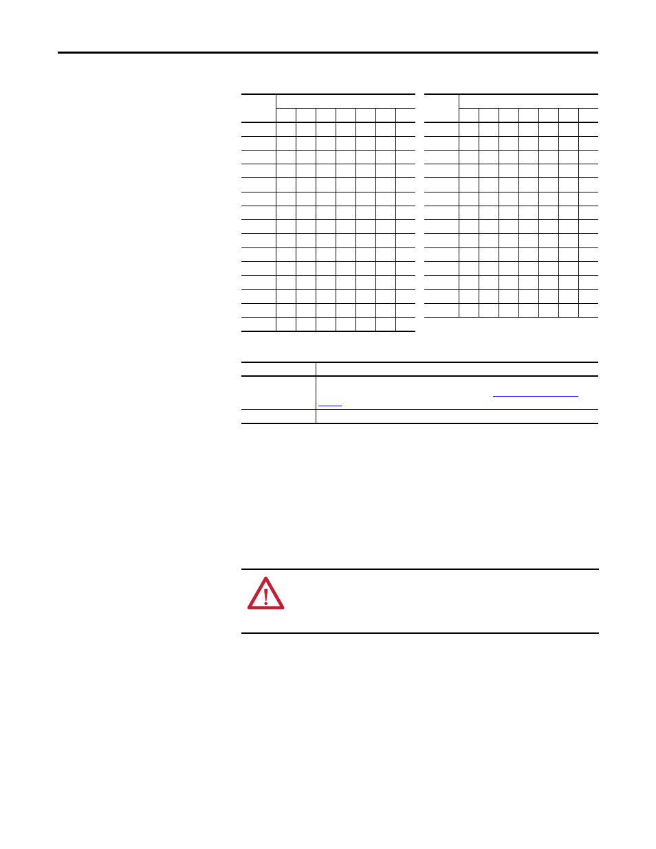
Node Address Switch Settings
Description of Node Address Switches
The switch settings can be verified by viewing the
Device parameter 06 [Net
Addr Act]
, a read-only parameter, with any of the following drive configuration
tools:
•
PowerFlex 520-series drive built-in keypad
•
PowerFlex 22-HIM-A3 or 22-HIM-C2S HIM
•
Connected Components Workbench software (version 3 or greater)
Connecting the Adapter to
the Drive
1.
Remove power from the drive.
2.
Use static control precautions.
3.
Separate the drive’s control module from the power module.
Node
Address
Node Address Switch
Node
Address
Node Address Switch
7
6
5
4
3
2
1
7
6
5
4
3
2
1
00
0
0
0
0
0
0
0
15
0
0
0
1
1
1
1
01
0
0
0
0
0
0
1
16
0
0
1
0
0
0
0
02
0
0
0
0
0
1
0
17
0
0
1
0
0
0
1
03
0
0
0
0
0
1
1
18
0
0
1
0
0
1
0
04
0
0
0
0
1
0
0
19
1
0
1
0
0
1
1
05
0
0
0
0
1
0
1
20
0
0
1
0
1
0
0
06
0
0
0
0
1
1
0
...
07
0
0
0
0
1
1
1
120
1
1
1
1
0
0
0
08
0
0
0
1
0
0
0
121
1
1
1
1
0
0
1
09
0
0
0
1
0
0
1
123
1
1
1
1
0
1
0
10
0
0
0
1
0
1
0
124
1
1
1
1
0
1
1
11
0
0
0
1
0
1
1
125
1
1
1
1
1
0
0
12
0
0
0
1
1
0
0
126
1
1
1
1
1
0
1
13
0
0
0
1
1
0
1
127
1
1
1
1
1
1
1
14
0
0
0
1
1
1
0
Node Address Value
Description
00 or 127
If the Node Address switches are set to ‘00’ (the default setting) or 127, the adapter uses Device
parameter 05 [Net Addr Cfg] to set the Node Address. See
01...126
Node Address used by the adapter.
ATTENTION: Risk of injury or death exists. The PowerFlex drive may contain
high voltages that can cause injury or death. Remove power from the drive, and
then verify power has been discharged before connecting the adapter to the
network.