Removing the rear cover of the bulletin 825-smm, Removing the rear cover, Of the bulletin 825-smm – Rockwell Automation 825-MDN Smart Motor Manager DeviceNet Communication Card User Manual User Manual
Page 12
Publication 825-UM002A-EN-P - December 2000
2-2 Installation
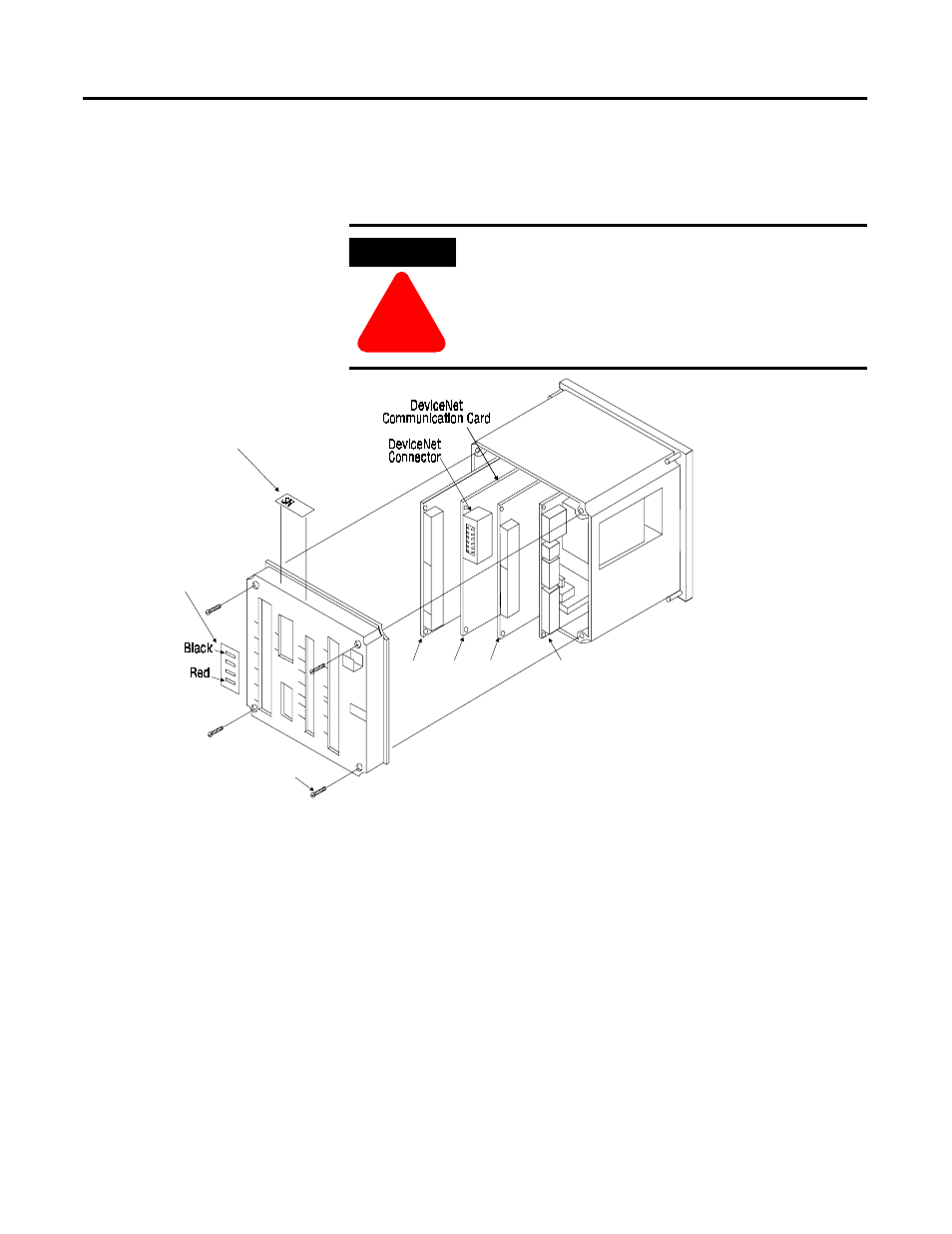
Removing the Rear Cover
of
the Bulletin 825-SMM
Before installing the Communication Card, the SMM’s rear cover must
be removed. This is done by removing the 4 screws on the corners of
the rear cover as shown in Figure 2.1.
Installing the
Communication Card in the
Bulletin 825-SMM
1.
Remove the previously installed Communication Card
➂
(if
necessary) by carefully pulling it out from the unit along the
guiding slots of the SMM housing.
2.
Align the new Communication Card in the second set of guiding
slots from the left with the component side facing the basic unit with
power supply
➄
. Carefully and slowly slide the Communication Card
into the SMM housing, making sure that backplane connector shown in
Figure 2.1 mates with the backplane receptacle pins on the
motherboard. Care should be taken not to damage the pins or backplane
connector while making sure that the Communication Card seats against
the motherboard.
ATTENTION
!
Ensure that you disconnect line power from the Bulletin
825 SMM before removing the rear cover.
➀
➁
➂
➃
➄
➅
➆
➇
➈
B
825-M Housing
Option 825-MMV or 825-MLV (if installed)
Communication Card
Option 825-MST (if installed)
asic Unit board with power supply
Rear cover
Screws
DeviceNet label
Serial # label
➀
➁
➂
➃
➄
➆
➅
➇
➈
Figure 2.1 Removing and Installing the Communication Card