Rockwell Automation 20C PowerFlex 700H Drives Programming User Manual
Page 67
Rockwell Automation Publication 20C-PM001F-EN-P - March 2012
67
Troubleshooting
Chapter 3
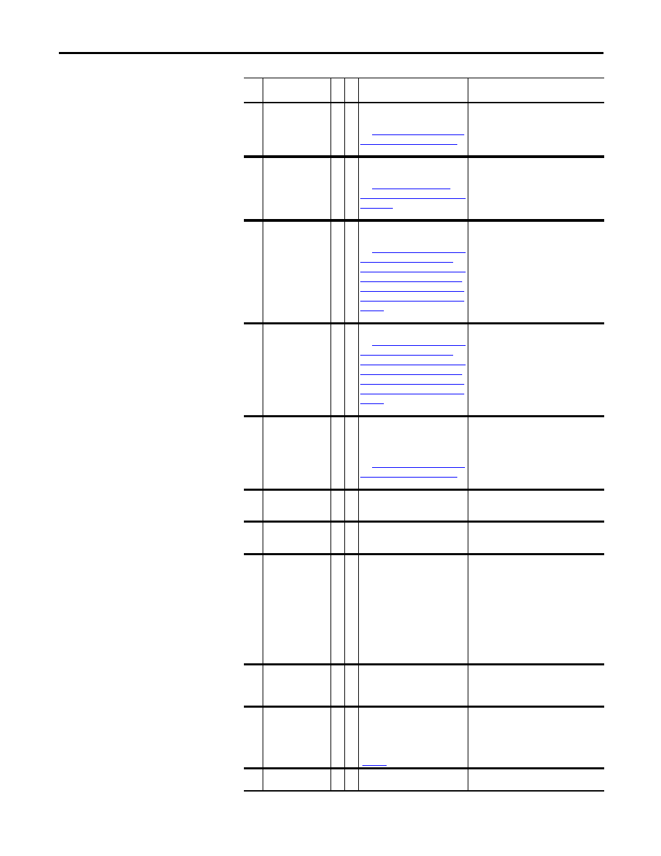
34
CAN Bus Flt
2
A sent message was not
acknowledged.
See
Fault (F34) Subcode,” on page 74
for more information on this fault.
1. Cycle the power.
2. Replace the Main Control board.
37
HeatsinkUndTp
1
The ambient temperature is too
low.
See
Temperature Fault (F37) Subcodes,”
on page 75
for more information on
this fault.
Raise the ambient temperature.
44
Device Change
2
The new power unit or option
board installed is a different type.
See
Table 21, “Device Change (F44),
for more information on
this fault.
Clear the fault and reset the drive to the
factory defaults.
45
Device Add
2
A new option board was added.
See
Table 21, “Device Change (F44),
for more information on
this fault.
Clear the fault.
47
NvsReadChksum
2
There was an error reading
parameters 9 [Elapsed MWh] and
10 [Elapsed Run Time] from
EEPROM.
See
Fault (F47) Subcode,” on page 76
for more information on this fault.
1. Cycle the power.
2. Replace the Main Control board.
48
ParamsDefault
2
The drive was commanded to write
default values to EEPROM.
1. Clear the fault or cycle power to the
drive.
2. Program the drive parameters as needed.
54
Zero Divide
2
This event occurred because a
mathematical function had a
dividend of zero.
1. Cycle the power.
2. Replace the main Control board.
59
Gate Disable
3
1 Both of the digital gate disable
inputs (SD-1 and SD-2) are not
enabled on the 20C-DG1 option
board.
1. Check the motor.
2. Verify that the option board is properly
wired.
3. Replace the option board. See Appendix
E - “Instructions for ATEX Approved
PowerFlex 700H Drives in Group II
Category (2) Applications with ATEX
Approved Motors” in the PowerFlex 700H
and 700S Drives Installation Manual,
publication PFLEX-IN006, for information
on installing this option board.
60
Hrdwr Therm
3
1 The thermistor input is activated
(>4 k
Ω
) on the 20C-DG1 option
board.
1. Check the motor.
2. The resistance of the thermistor input
must go below 2 k
Ω
before the drive can
be reset.
63
Shear Pin
3
The value programmed in
parameter 148 [Current Lmt Val]
has been exceeded. You can
enable/disable this fault with
parameter 238 [Fault Config 1]
(
Check the load requirements and the value
in [Current Lmt Val].
65
I/O Removed
2
An I/O option board has been
removed.
Clear the fault.
No. Name
Fa
u
lt
Alarm
Description
Action (if applicable)